


AT-RPS3000 Redundant Power Supply Installation Guide
17
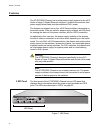
Power Supply
Slots
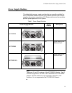
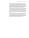
The slots on the back panel of the chassis are for two power supply
modules. The slots are labeled A and B.
Figure 2. Slots A and B for the Power Supply Modules
Note
The chassis is shipped from the factory with a blank panel over the
power supply slots.
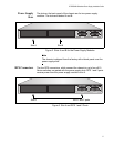
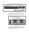
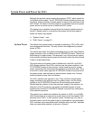
RPS Connectors The four RPS connectors, which connect the chassis to up to four x610
Series switches, are paired with the power supply slots. RPS 1 and 2 ports
receive power from the power supply module in slot A.
Figure 3. Slot A and RPS 1 and 2 Ports
Slot A Slot B
2166
B
B
1
2
3
4
SYSTEM
PoE+ / SYSTEM PoE+ / SYSTEM
SYSTEM
MODULE B
MODULE A
A
A
Slot A RPS 1 and 2 ports
2166
B
B
1
2
3
4
SYSTEM
PoE+ / SYSTEM PoE+ / SYSTEM
SYSTEM
MODULE B
MODULE A
A
A