


Chapter 1: Overview
42
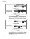
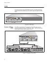
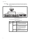
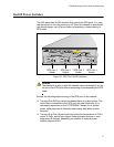
LEDs
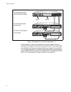
On the front panel of the AT-RPS3000 Chassis is an LED panel that
displays status information about the power supply modules and RPS
ports.
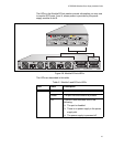
Figure 26. LED Panel
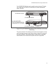
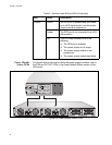
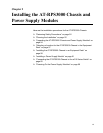
Module A/B Ports
LEDs
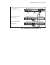
The LEDs in the Module A Ports section of the LED panel provide
information about the status of RPS ports 1 and 2, which receive their
power from the power supply module in slot A.
Figure 27. Module A Ports LEDs
2148
LED Panel
B
B
1
2
3
4
SYSTEM
PoE+ / SYSTEM PoE+ / SYSTEM
SYSTEM
MODULE B
MODULE A
A
A
AT-PWR800
DC OUT
FAULT
100-240 VAC~12A MAX
AT-PWR800
DC OUT
FAULT
100-240 VAC~12A MAX
2156