


AT-RPS3000 Redundant Power Supply Installation Guide
29
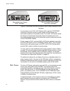
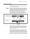
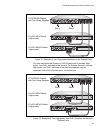
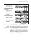
Figure 12. Example of Two High-power Switches on the System Ports
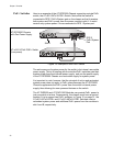
You may use either the System or PoE+/System port to connect high-
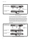
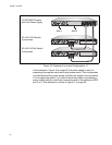
power, non-PoE+ switches to the chassis. To illustrate this point, the two
high-power, non-PoE+ switches in the previous example may be
connected to the PoE+/System ports, as shown here.
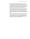
Figure 13. Example of Two High-power, Non-PoE+ Switches on the PoE+/
System Ports
AT-x610-48Ts Switch
AT-x610-48Ts/X Switch
AT-RPS3000 Chassis
(High-power)
(High-power)
with Two Power Supplies
B
B
1
2
3
4
SYSTEM
PoE+ / SYSTEM PoE+ / SYSTEM
SYSTEM
MODULE B
MODULE A
A
A
AT-PWR800
DC OUT
FAULT
100-240 VAC~12A MAX
AT-PWR800
DC POWER
FAULT
100-240 VAC~12A MAX
100-240 VAC~12A MAX
POWER SUPPLY
RPS
READY
RPS INPUT
12V/21A MAX
WARNING
This unit may have more than one power input. To reduce the risk of
electric shock, disconnect both A/C and RPS inputs before servicing
unit.
100-240 VAC~12A MAX
POWER SUPPLY
RPS
READY
RPS INPUT
12V/21A MAX
WARNING
This unit may have more than one power input. To reduce the risk of
electric shock, disconnect both A/C and RPS inputs before servicing
unit.
2136
Slot A Slot B
B
B
1
2
3
4
SYSTEM
PoE+ / SYSTEM PoE+ / SYSTEM
SYSTEM
MODULE B
MODULE A
A
A
AT-PWR800
DC OUT
FAULT
100-240 VAC~12A MAX
AT-PWR800
100-240 VAC~12A MAX
DC OUT
FAULT
100-240 VAC~12A MAX
POWER SUPPLY
RPS
READY
RPS INPUT
12V/21A MAX
WARNING
This unit may have more than one power input. To reduce the risk of
electric shock, disconnect both A/C and RPS inputs before servicing
unit.
100-240 VAC~12A MAX
POWER SUPPLY
RPS
READY
RPS INPUT
12V/21A MAX
WARNING
This unit may have more than one power input. To reduce the risk of
electric shock, disconnect both A/C and RPS inputs before servicing
unit.
2139
AT-x610-48Ts Switch
AT-x610-48Ts/X Switch
AT-RPS3000 Chassis
(High-power)
(High-power)
with Two Power Supplies
Slot A
Slot B