


AT-RPS3000 Redundant Power Supply Installation Guide
81
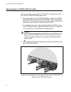
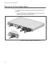
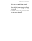
6. If you are not replacing the module, cover the empty slot with one of
the slot covers, labeled AT-PNL250 and AT-PNL800/1200, provided
with the unit.
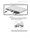
The faceplates of the power supply modules and the slot covers are
keyed so that the slot cover has to correspond to the power supply
module you installed in the unit. Use the AT-PNL250 Blank Panel if the
chassis contains the AT-PWR250 Power Supply Module, or the
AT-PNL800/1200 Blank Panel if it has the AT-PWR800 or
AT-PWR1200 Power Supply Module.
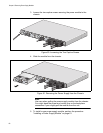
Figure 62. Installing the Slot Cover
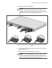
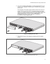
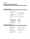
7. Secure the slot cover to the chassis by tightening the two captive
screws.
Figure 63. Securing the Slot Cover
B
B
1
2
3
4
S
Y
S
T
E
M
P
o
E
+
/
S
Y
S
T
E
M
P
o
E
+
/
S
Y
S
T
E
M
S
Y
S
T
E
M
M
ODULE
B
MODULE A
A
A
AT-PWR800
D
C
O
U
T
F
A
U
L
T
AT-PNL800/
1200
2173
100-240 VAC
~12A
MAX
B
B
1
2
3
4
SYSTEM
PoE+ /
SY
S
TEM
PoE+ /
SY
STEM
SYSTEM
MODULE B
MODULE A
A
A
A
T
-
P
N
L
8
0
0
/
1
2
0
0
AT-PWR800
DC OU
T
FAULT
2174
1
0
0
-2
4
0
V
A
C
~
1
2
A
M
A
X