


Chapter 2: Installing the AT-RPS3000 Chassis and Power Supply Modules
64
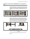
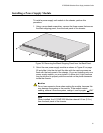
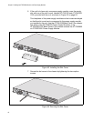
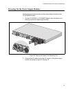
6. If the unit is to have only one power supply module, cover the empty
slot with one of the slot covers, labelled AT-PNL250 and AT-PNL800/
1200, provided with the unit, as shown in Figure 43 on page 64.
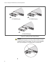
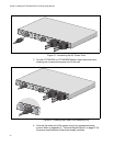
The faceplates of the power supply modules and slot covers are keyed
so that the slot cover has to correspond to the power supply module
you installed in the unit. Use the AT-PNL250 Blank Panel if the chassis
has either of the AT-PWR250 Power Supply Modules, or the
AT-PNL800/1200 Blank Panel if the chassis contains the AT-PWR800
or AT-PWR1200 Power Supply Module.
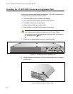
Figure 43. Installing the Slot Cover
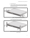
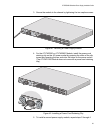
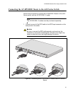
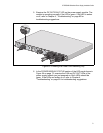
7. Secure the slot cover to the chassis by tightening the two captive
screws.
Figure 44. Securing the Slot Cover
B
B
1
2
3
4
S
Y
S
T
E
M
P
o
E
+
/
S
Y
S
T
E
M
P
o
E
+
/
S
Y
S
T
E
M
S
Y
S
T
E
M
MODULE B
MODULE A
A
A
AT-PNL800/
1200
AT-PWR800
D
C
O
U
T
F
A
U
L
T
100-240
VAC
~12A
MAX
2150
B
B
1
2
3
4
S
Y
S
T
E
M
P
o
E
+
/ S
Y
S
T
E
M
P
o
E
+
/
S
Y
S
T
E
M
S
Y
S
T
E
M
MODULE B
MODULE A
A
A
AT-PWR800
D
C
O
U
T
F
A
U
L
T
AT-
PNL800/1200
2175
100-240
VAC
~12A MAX