


Chapter 2: Installing the AT-RPS3000 Chassis and Power Supply Modules
72
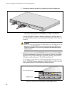
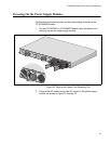
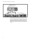
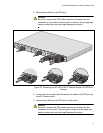
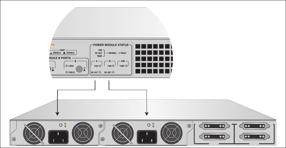
Figure 54. Checking the FAN and DC OUT LEDs in the LED Panel
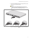
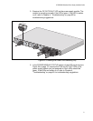
7. In the MODULE A/B PORTS section of the LED panel shown in Figure
55 on page 73, examine the LOAD and CABLE LEDs of the two ports
that receive power from the power supply module. The LOAD and
CABLE LEDs of RPS ports that are connected to x610 Series switches
should be green. If the LEDs are off, press the On/Off buttons to active
the ports.
B
B
1
2
3
4
SYSTEM
PoE+ / SYSTEM PoE+ / SYSTEM
SYSTEM
MODULE B
MODULE A
A
A
AT-PWR800
DC OUT
FAULT
100-240 VAC~12A MAX
AT-PWR800
DC OUT
FAULT
100-240 VAC~12A MAX