


SwitchBlade x3112 Installation Guide
53
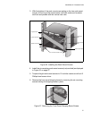
2. Ensure that the following hardware components are included in your
package. If any item is missing or damaged, contact your Allied Telesis
sales representative for assistance.
– One AT-SBx3112 Chassis (with pre-installed AT-
SBx31FAN Tray and shipping brace)
– Ten line card blank panels
– Three power supply blank panels
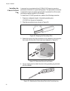
Adjusting the
Brackets
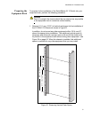
Before installing the AT-SBx3112 Chassis, you need to determine where
the horizontal position of the chassis front panel will be relative to the
vertical rack rails. The AT-SBx3112 Chassis rack mounting brackets come
installed from the factory so that the chassis is flush with the rack rails after
installation. See position “A” in
Figure 23 on page 54.
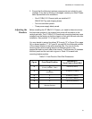
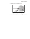
You may decide to extend (positions “B” through “E” in Figure 23 on page
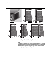
54) or recess (position “F” in Figure 24 on page 55) the horizontal position
of the chassis relative to the rack mounting rails. You can do this by
removing both rack mounting rails and re-attaching them in the
appropriate holes on each side of the chassis. The dimension (X) between
the front panel and the rack rails is given in
Table 13 for each rack
mounting bracket position.
Table 13. Front Panel to Rack Rail Dimensions
Figure Front Panel Position
Dimension X
Front Panel to Rack Rail
19 A
(Factory Installed - Flush)
3.69 mm (0.145 in)
19 B
(Recessed)
-27.39 mm (-1.078 in)
19 C 27.39 mm (1.078 in)
19 D 47.71 mm (1.878 in)
19 E 140.85 mm (5.545 in)
20 F
(Reverse Position)
374.16 mm (14.731 in)