


Chapter 4: Installing the Power Supplies
104
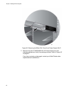
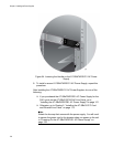
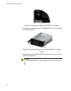
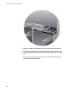
Figure 58. Verifying the AT-SBxPWRPOE1 AC Power Supply
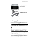
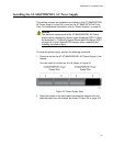
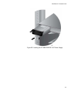
5. Raise the locking handle on the AT-SBxPWRPOE1 AC Power Supply,
as shown Figure 59.
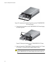
Figure 59. Raising the Handle on the AT-SBxPWRPOE1 AC Power
Supply
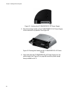
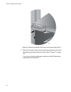
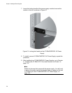
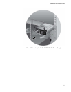
6. Align and insert the AT-SBxPWRPOE1 Module into slot A or B. See
Figure 60 on page 105.
Caution
The AT-SBxPWRPOE1 AC Power Supply will not work in slot C or
D.