


Chapter 1: Overview
64
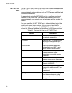
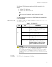
The LEDs on the AT-SBxPWRPOE1 AC Power Supply are described in
Table 19.
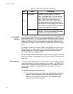
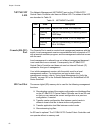
Table 18. LEDs on the AT-SBxPWRSYS1 DC Power Supply
LED State Description
DC
IN
Solid Green The power supply is receiving DC power that is
within the normal operating range.
Off The power supply is not receiving power from the
DC power source.
DC
OUT
Solid Green The DC power that the module is providing to the
chassis components is within the normal
operating range.
Off The power supply is not generating DC power or
the power is outside the normal operating range.
Fault
Solid Amber The power supply has detected a fault condition,
such as an under-voltage, or over-temperature
condition.
Off The power supply is operating normally or is
powered off.
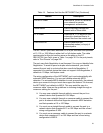
Table 19. LEDs on the AT-SBxPWRPOE1 AC Power Supply
LED State Description
AC
Solid Green The power supply is receiving AC power that is
within the normal operating range.
Off The power supply is not receiving power from the
AC power source.
DC
Solid Green The DC power provided by the module over the
backplane to the AT-SBx31GP24 PoE Line Cards
and the powered devices is within the normal
operating range.
Off The power supply is not providing any DC power
or the power is not within the normal operating
range.
Fault
Solid Amber The power supply has detected a fault condition,
such as an under-voltage or over-temperature
condition.
Off The power supply is operating normally or is
powered off.