


SwitchBlade x3112 Installation Guide
107
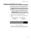
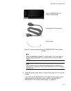
Installing the AT-SBxPWRSYS1 DC Power Supply
This section contains the installation procedure for the AT-SBxPWRSYS1
DC Power Supply. For background information, refer to “Power Supplies”
on page 62.
Caution
The electronic components in the AT-SBxPWRSYS1 DC Power
Supply can be damaged by electro-static discharges (ESD). Follow
the procedure in “Protecting Against Electrostatic Discharge (ESD)”
on page 94 to guard against ESD damage when unpacking and
installing the power supply.
To install the power supply, perform the following procedure:
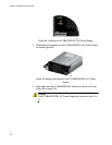
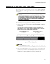
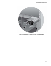
1. Choose a slot in the chassis for the AT-AT-SBxPWRSYS1 DC System
Power Supply.
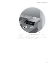
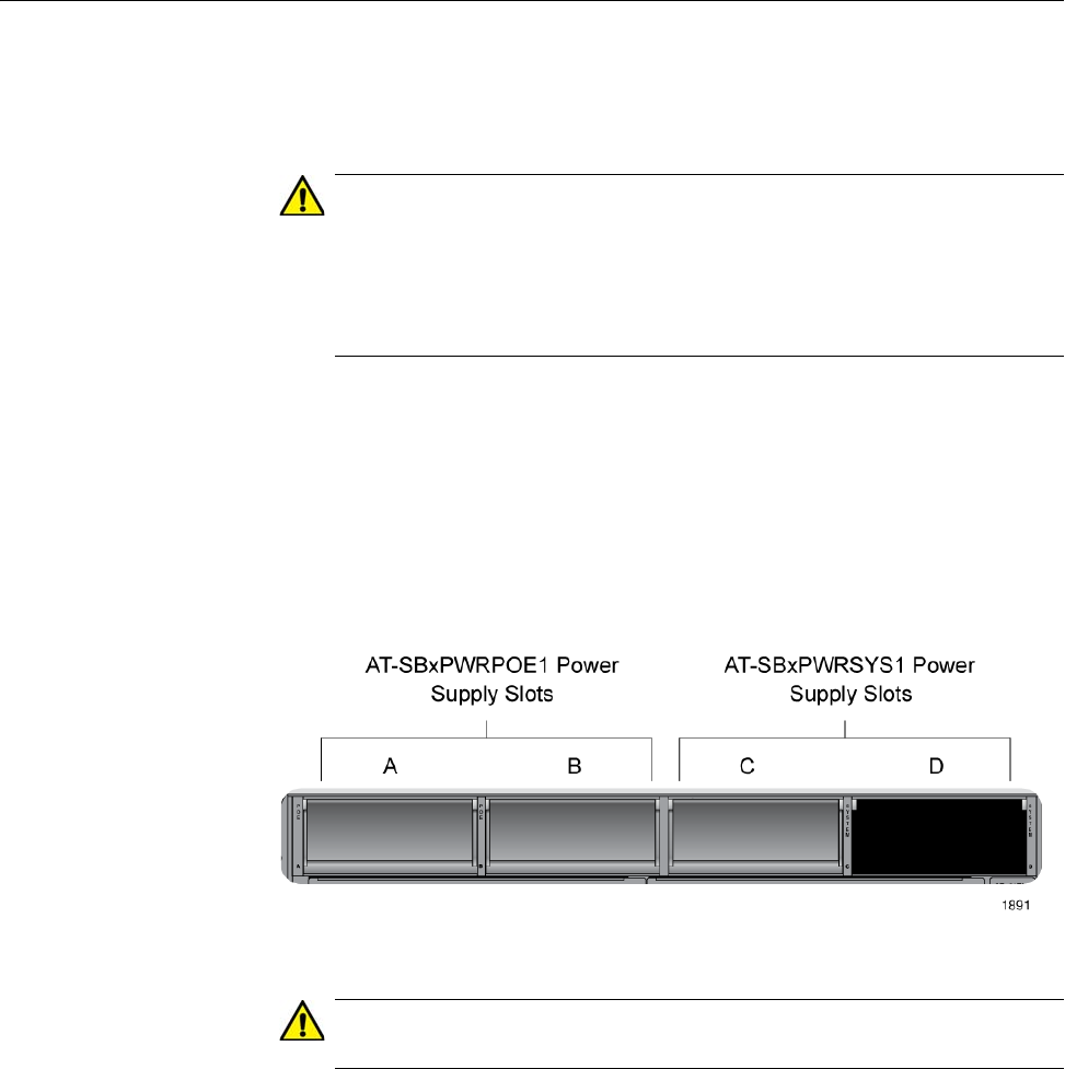
You may install it in slot C or D, shown in Figure 62. The first AT-
SBxPWRSYS1 Power Supply should be installed in slot D, because
the slot does not have a blank power supply panel.
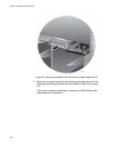
Figure 62. Power Supply Slots
Caution
The AT-SBxPWRSYS1 DC Power Supply will not work in slot A or B.
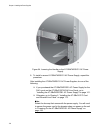
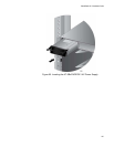
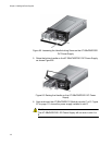
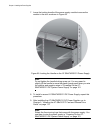
2. If the chassis already has a power supply in slot D, remove the blank
power supply panel from slot C by lifting the blank panel handle and
sliding it out of the slot, as shown in Figure 63 on page 108.