


BGP and BGP4+ Configuration
Software Reference Supplement for SwitchBlade® x8112, x908, x900 and x610 Series Switches
2.26 AlliedWare Plus
TM
Operating System - Software Version 5.4.3-2.6 C613-50032-01 REV D
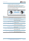
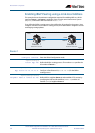
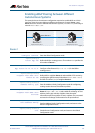
Enabling iBGP Peering using a Link-local Address
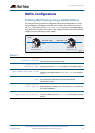
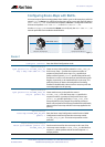
This example shows the minimum configuration required for enabling iBGP on a VLAN
interface. Router 1 and Router 2 are BGP4+ Peers in in the same Autonomous System
(AS), 200, connected to link local network fe80::/10.
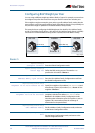
First, define the BGP4+ routing process, then define the AS number for the routers. Next,
configure a Router ID for the BGP4+ routing process, then define BGP4+ neighbors to start
exchanging routing updates.
Router 1
bgp4+_2
Router ID 10.10.10.11 Router ID 10.10.10.12
AS200
Router 1
fe80::1
Router 2
fe80::2vlan1
vlan2
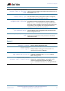
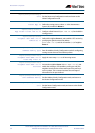
awplus#
configure terminal
Enter the Global Configuration mode.
awplus(config)#
router bgp 200
Define the BGP4+ routing process. The number 200 specifies the
AS number of Router 1.
awplus(config-router)#
bgp router-id 10.10.10.11
Configure a fixed Router ID (10.10.10.11) for the BGP4+
routing process.
awplus(config-router#
neighbor fe80::2 remote-as 200
Define BGP4+ neighbor Router 2, and establish a TCP session by
specifying the link-local IPv6 address (fe80::2) and the AS
number (200) of neighbor Router 2.