


Chapter 1: Overview
22
.
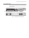
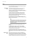
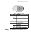
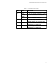
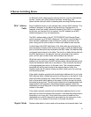
Figure 4. 10/100Base-T Non-PoE Port LEDs
Uplink Combo
Port LEDs
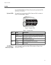
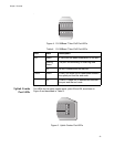
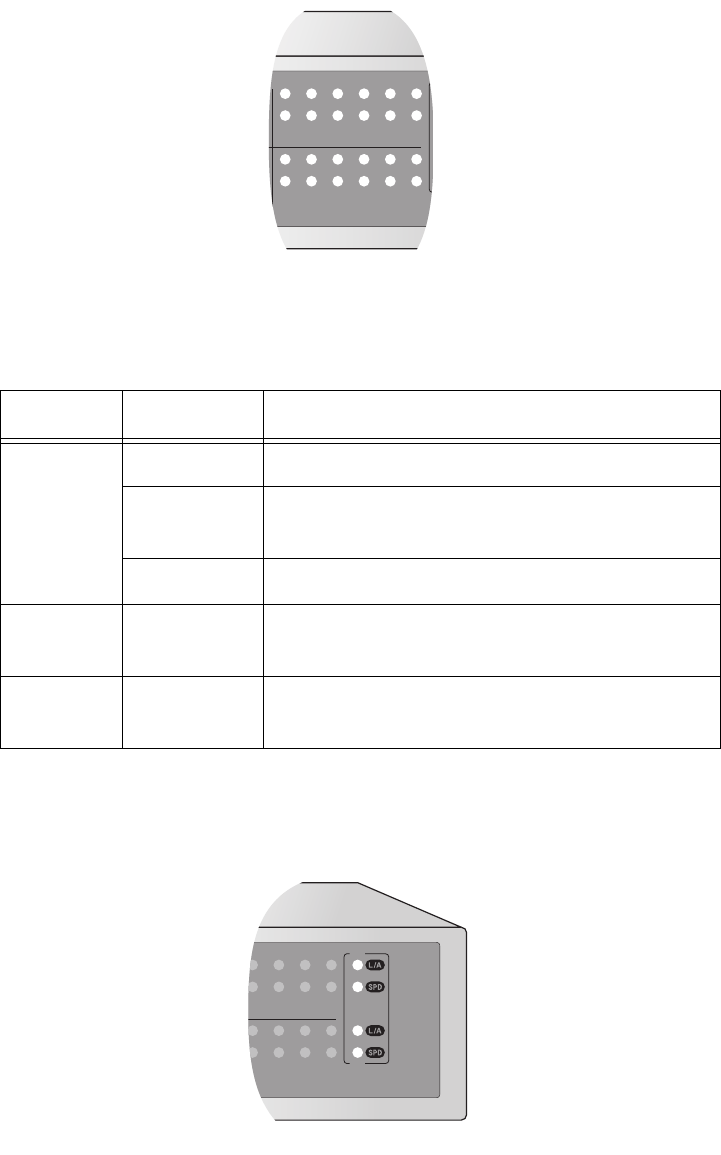
The LEDs for the uplink combo ports, ports 25 and 26, are shown in
Figure 5 and described in Table 5.
Figure 5. Uplink Combo Port LEDs
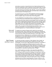
Table 4. 10/100Base-T Non-PoE Port LEDs
LED State Description
L/A Green A valid link has been established on the port.
Blinking
Green
The port is transmitting or receiving data.
Off No link is established on the port.
100M Green A valid 100 Mbps link is established between
the uplink port and the end node.
Off A valid 10 Mbps link is established between
the port and the end node.
13
14
15
16
17
18
19
20
21
22
23
24
1094
17
18
19
20
21
22
23
24
25
26
1095