


7
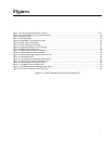
Figure 1: RJ-45 Connector and Port Pin Layout............................................................................................................... 52 7
Figure 2: AT-FS750/24POE Front and Back Panels ........................................................................................................... 17
Figure 3: System LEDs........................................................................................................................................................ 20
Figure 4: POE Port LEDs .................................................................................................................................................... 21
Figure 5: 10/100Base-T Non-PoE Port LEDs...................................................................................................................... 22
Figure 6: Uplink Combo Port LEDs...................................................................................................................................... 22
Figure 7: Power Workgroup Topology................................................................................................................................. 30
Figure 8: Collapsed Backbone - Hub Topology................................................................................................................... 31
Figure 9: Attaching the Rubber Feet ................................................................................................................................... 39
Figure 10: Attaching the Rack-Mount Bracket..................................................................................................................... 40
Figure 11: Mounting the Switch on the Rack....................................................................................................................... 40
Figure 12: Removing the Dust Plug from the SFP Slot ....................................................................................................... 43
Figure 13: Inserting the SFP................................................................................................................................................ 44
Figure 14: Connecting the Twisted Pair Data Cables.......................................................................................................... 45
Figure 15: Removing the Dust Plug from the SFP............................................................................................................... 46
Figure 16: Connecting the Fiber Optic Cable ...................................................................................................................... 46
Figure 17: Plugging in the AC Power Cord.......................................................................................................................... 47
Figure 18: AT-S88 Management Software Main Page........................................................................................................ 48
Figure 19: RJ-45 Connector and Port Pin Layout................................................................................................................ 52
Figure 1. RJ-45 Connector and Port Pin Layout 52
Figures