


AT-FS750/24POE Fast Ethernet Smart Switch Installation Guide
45
Cabling and Powering On the Switch
Connecting the
Twisted Pair
Cables
To connect the twisted cables to the RJ-45 ports on the AT-FS750/24POE
Fast Ethernet Smart switch, perform the following procedure:
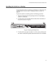
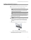
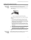
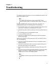
1. Plug the twisted pair data cables to the RJ-45 ports on the switch, as
shown in Figure 13.
Figure 13. Connecting the Twisted Pair Data Cables
When connecting a twisted pair cable to a port, observe the following
guidelines:
An RJ-45 connector should fit snugly into the port on the switch.
The tab on the connector should lock the connector into place.
The ports on the switch are auto-MDI/MDI-X. You can use either a
straight-through or crossover twisted pair cable to connect any type
of network device to a port on the switch.
The network should not contain data loops, which can adversely
affect network performance. A data loop exists when two or more
network devices can communicate with each other over more than
one data path.
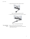
2. Connect the other end of the twisted pair cable to a port in the end
node.
Connecting the
Fiber Optic
Cables
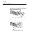
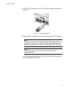
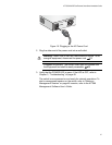
To connect a fiber optic cable to an SFP installed in the AT-FS750/24POE
Fast Ethernet Smart switch, perform the following procedure:
1
3
5
7
24
6
8
P
O
E
PW
R
SYSTEM
10/
1
00
P
OE PO
R
T
S
1101
Warning: To reduce the risk of electric shock, the PoE ports on
this product must not connect to cabling that is routed outside
the building where this device is located.
E40