


SWITCHERS
9
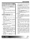
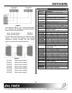
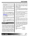
values connected to ground any channel can be
selected. Although the channel selection by the
relay contact is latching and will maintain the last
relay-selected channel, it is recommended that
momentary contact closures are not used. Typical
resistor values and wires connections are shown
below.
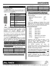
Figure 3
In some cases it may be preferable to use a five
conductor wire to control the switcher with contact
closures. The RC5204CC adapter is available to
accommodate this need. The pin outs for this
adapter are as follows:
9 pin “D”
Male
Description 9 pin “D”
Female
Input
7 1.2K 1 1
7 3.3K 2 2
7 6.8K 3 3
7 12K 4 4
7 0 short 7 NONE
5 Ground 9
The following voltages apply for selecting the
required channel:
Input number min. (V) nom. (V) max. (V)
1 0.35 0.55 0.75
2 1.07 1.27 1.47
3 1.80 2.00 2.20
4 2.52 2.72 2.92
These voltage levels can be set using analog
outputs from different control systems or spare
dimmer control outputs.
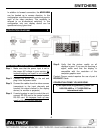
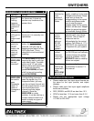
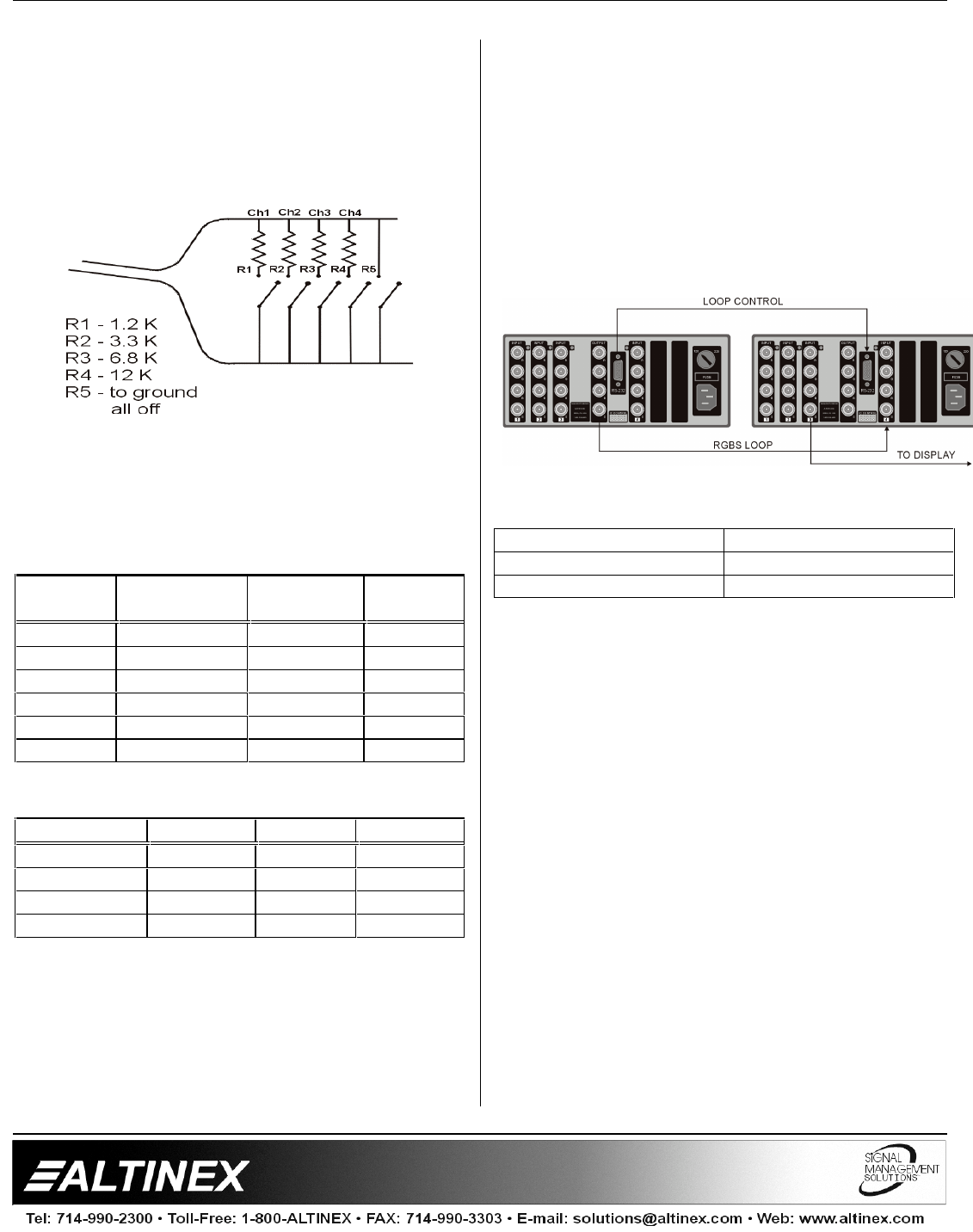
7.5 MANUAL LOOP CONTROL
Loop control is used when multiple units of the
MX2214RM are connected together to form a
single switcher. When the input channel button is
pressed the loop control pin is internally grounded
and the MX2214RM Switcher selects INPUT 4 as
the default input.
In this configuration the loop control pin 6 on the 9
pin D connector is connected to the same pin on all
switchers.
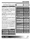
Figure 4
MX2214RM LOOP MX2214RM LOOP
6 6
5 5
MX2214RM 9-pin “D” Loop
The loop control pin has an internal 100k resistor to
+5volts. This limits the number of switchers that
can be looped to a maximum of 10 switchers,
which can be daisy chained together using this
method.
More specifically, the output of one switcher is
connected to INPUT 4 of the next switcher. Once
loop control is enabled these switchers will
automatically switch video signals to the output of
the second switcher through INPUT 4. Keep in
mind that you are always going to have one less
input than the total number of inputs available on
all switchers. Figure 4 above is for a 7-in 1-out
Switcher.
7.6 LOOP CONTROL WITH RS-232 COMMAND
When multiple MX2214RM units are connected
together to get a single switcher and RS-232
commands are used to control these units, please
connect units according to Figure 5.