


SWITCHERS
5
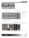
The front panel of the MX2214RM provides access
to essentially all of the switcher’s capabilities. In
addition to standard switching functions, the unit has
control and switching functions that could be very
useful in a variety of special applications.
4.1 SELECT INPUT
When buttons 1 through 4 are pressed, the
corresponding INPUT will be selected and
displayed. LED’s on the front and rear panels will
light simultaneously to indicate which selection has
been made.
4.2 AUTO SWITCH MODE BUTTON
This function is not operational at this time and is
reserved for future upgrades.
4.3 STAND BY / ALL CHANNELS OFF BUTTON
This function allows a user to turn OFF all input
signals. It is very useful when the MX2214RM
Switcher is used in applications where there is a
need to turn the display or the source OFF. Press
this function key (F2) to switch to a no signal
condition. The LED next to the F2 will light to
indicate that it is in this mode. To resume input
select switching, simply press the desired INPUT.
4.4 RESET BUTTON
This function allows a user to RESET the switcher
without unplugging the unit. Press the function key
RESET (F3) and hold it for 2 seconds. When you
hear a beeping sound, release the key. All of the
LED’s will flash simultaneously. The switcher is
now reset. All previous defaults, such as power on
channel default and other user settings are
maintained.
4.5 BEEP ON/OFF BUTTON
This function allows a user to have an audible
feedback when buttons are pressed. The factory
default is beep ON. However, in some applications,
sound may be undesirable. To disable sound,
press this function key (F4) and hold it for
approximately 2 seconds until a beeping sound is
heard. The function is now disabled. To enable it,
repeat the same steps. The setting is stored in the
memory and is maintained during the power up
sequence.
4.6 POWER UP DEFAULT SET
This function allows a user to select the channel
that will be ON at power up. To select the default
channel, press the selected channel switch and
hold it for approximately 2 seconds until you hear a
beeping sound. If the unit is turned off and turned
on again, the LED of the selected channel should
light.
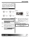
4.7 ANALOG OUTPUT
The analog output of the MX2214RM can be used
for controlling several switchers simultaneously.
The analog amplifier drives analog output pin 9 on
a 9-pin “D” connector. The output can switch from
0 V to approximately 5.0 V. The output impedance
of this pin is 100 Ohms and it can sink or source up
to 5 mA of current. By using this output, several
switchers can operate in gang mode. To do this,
the analog output of the master switcher (pin 9) is
connected to the analog input of the slave
switchers (pin 9). Now, every time a channel is
selected on the master switcher, the output voltage
of the analog output will be set to switch all other
switchers into the same channel. The simplicity of
this approach is that only two wires (one to pin 9
and one to ground) are required to connect and
control all of the switchers. The selection of
channels can also be accomplished by RS-232 on
the master switcher with all slave switchers
connected through the analog control pin. A
maximum of four switchers can be connected in
this configuration.
4.8 POWER SUPPLY
The MX2214RM Switcher has 5 V power supply
available on pin 8 of the 9-pin “D” connector. This
voltage can be used to drive external circuits or as
a pull up voltage for open collector type outputs.
The total current on this pin should not exceed 150
mA continuous operation or 500 mA for 5 minutes.
4.9 BI-DIRECTIONAL SWITCHING
The MX2214RM Switchers use very high
bandwidth relays to provide you with 400 MHz
bandwidth. Each input, when not selected, is
terminated to 75 Ohms resistor. This is done to
make sure that the video lines are always
terminated whether a channel is selected or not.