


SWITCHERS
7
OPERATION 7
7.1 RS-232 CONTROL
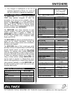
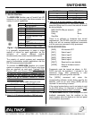
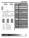
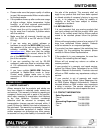
The MX2214RM Switcher uses a Female 9-pin HD
connector on its rear panel that allows access to a
variety of control capabilities.
PIN No. PIN Designation
1 No connection
2 RS-232 Transmit
3 RS-232 Receive
4 No connection
5 Ground
6 Multiple Switcher Loop
Control
7 Analog Switch Voltage
Input
8 +5 V (150 mA max)
9 Analog Voltage Output
Figure 1: 9-pin D connector
It is generally recommended to select a single
method of control for each application, as the
activation of several different controls
simultaneously may cause unpredictable results.
The majority of control systems and computers
used in presentation system applications use the
RS-232 communications standard.
To connect the MX2214RM Switcher to a control
system or computer for RS-232 Control, only three
pins are required on each port: Transmit (TX),
Receive (RX), and Ground (GND). The Transmit
pin from the control system or computer must be
connected to the Receive pin of the switcher’s
Control Port; do not connect Transmit to Transmit
or Receive to Receive.
The following are typical cable wiring pin outs:
IBM PIN No.
MX2214RM PIN No.
3 2
2 3
7 5
Connection of IBM-PC 25-pin D to MX2214RM 9-pin
D. Note: 5, 6, 20 shorted together in IBM side only.
IBM PIN No.
MX2214RM PIN No.
2 2
3 3
5 5
Connection of IBM-PC 9-pin D to MX2214RM 9-pin
D. Note: 4, 6, 8 shorted together in IBM side only.
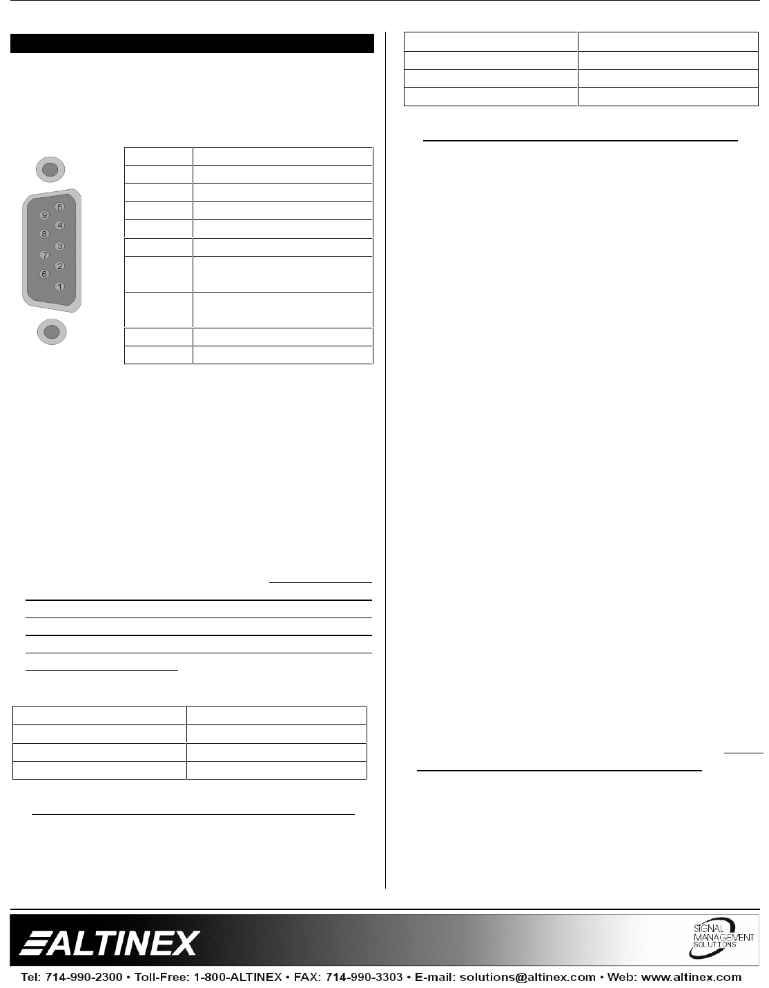
Port setting preferences for the control system or
computer being used to control the switcher should
be set as follows:
BAUD RATE (Bits per second) 2400
Data bits 8
Parity None
Stop Bits 1
There is no software or hardware flow control
implemented. The RS-232 input has a 6-character
buffer and will not execute additional commands
until the previous command is fully processed.
7.2 RS-232 PROTOCOL
[INP0] All channels OFF
[INP1] Select Input 1
[INP2] Select Input 2
[INP3] Select Input 3
[INP4] Select Input 4
[RSET] Reset unit to user defaults
[VERN] Returns firmware version
numbers
Commands must be issued as shown, in ALL
CAPS and with the brackets [ ] included in the
command string. After processing a valid
command, an [OK] string will be returned.
The [VERN] command will return the
corresponding software version being used by the
switcher, such as an error string. [ERR] will be
returned if is error string is issued.
If the control system being used is not setup to wait
for the [OK] string, it is important to include a 100
millisecond delay between each command.
The MX2214RM Switcher is also designed to send
feedback commands from the switcher to the
control system when the buttons on the front panel
of the switcher are pressed.