


SWITCHERS
8
The feedback codes are as follows:
Key
pressed
Description Feedback
Code
1 Input Select [INP1]
2 Input Select [INP2]
3 Input Select [INP3]
4 Input Select [INP4]
STAND BY All Outputs OFF [INP0]
RESET Reset [RSET][INPx]
The following commands are added to the
standard set of commands in order to facilitate the
control of multiple units using single RS-232 control
ports. These commands are available on the
switcher that has the firmware revision number:
2.0. Use [VERN] commands to determine the
firmware revision. These commands add additional
flexibility to the switcher.
[InnOmm]
nn - Input Number 00 to 99
mm - Output Number 01-99
This command connects any input to any output.
The switching occurs as soon as the command is
completed. The input 00 is used to disconnect a
particular output from any input. For example, the
command [I00O01] will disconnect output 1 from
any input.
[OUTmm]
This command sets the switcher to respond to a
specific output only. The default setting is output 1.
[SETxnnmm]
x - select input number
nn - Minimum input number
mm - Maximum input number
This command is designed to allow the MX2214RM
to program each of the inputs to respond to a
selected range of input commands.
For example, if command [SET10104] is issued,
then the following commands will select only Input
1: [I01O01], [I02O01], [I03O01], [I04O01]. In other
words a range of I/O commands can address the
same input. Default settings for each input is as
follows: Input 10101, Input 20202, Input 30303, &
Input 40404.
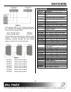
7.3 MASTER-SLAVE CONFIGURATION
These feedback codes allow multiple MX2214RM
Switchers to be connected in a Master-Slave
configuration, if desired.
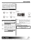
When the control ports of two units are connected
as shown below, the slave unit duplicates the
actions of the master unit. The same unit can still
be controlled from its front panel or through
another RS-232 control.
MX2214RM 9-pin D
Master PIN No.
MX2214RM 9-pin D
Slave PIN No.
2 3
5 5
Master-Slave Control Port Connection
A Master-Slave configuration can be achieved also
by Analog Switch Voltage using pin#9 and pin#7.
MX2214RM 9-pin D
Master PIN No.
MX2214RM 9-pin D
Slave PIN No.
9 7
5 5
Master-Slave Analog Switch Voltage Connection
With this configuration the master unit has ultimate
control over slave unit.
Figure 2
7.4 CONTACT CLOSURE (ONE WIRE ANALOG)
CONTROL
The one wire control is an alternative to a multi-
wire contact closure control. This control pin allows
you to select different channels based on the DC
voltage level on pin 7 of the 9 pin D connector.
Internally, pin 7 is pooled up to 5 volts by 10k
resistor. Thus, by selecting the proper resistor