SWITCHERS
400-0099-003 5
4.1 FRONT PANEL CONTROLS
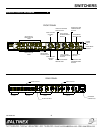
There are two sections on the front panel of the
MX2456RM: input-select and switcher-control. The
buttons within the input-select section allow for the
actual switching of the source signals. The buttons
within the switcher-control section allow access to
the switcher setup features.
4.1.1 VIDEO SELECT MODE
By default, video and audio inputs connect to video
and audio outputs simultaneously. If needed, the
user may select video and audio inputs separately
using AUDIO BREAK-AWAY mode. The user can
select any video input by using the input select
buttons located on the front panel.
4.1.2. AUDIO BREAK-AWAY MODE
This mode allows independent selection of video
and audio inputs. After selecting the
AUDIO BREAK-AWAY mode, the user may select
any audio or video input for switching.
4.1.3. EQUALIZATION MODE
Video signals are connected from input to output
through a video amplifier along with an equalization
circuit. This allows the user to equalize video signals
for each of the inputs according to the distance
(cable length) from the video source (PC) to the
switcher.
4.1.4. AUTO-SWITCH MODE
If AUTO-SWITCH mode is turned ON, the input
previously selected by the incoming video signal will
connect to the output automatically.
If the user does not previously select the
AUDIO BREAK-AWAY mode, the same number of
audio inputs will be connected to the audio output.
4.1.5. AUTO-ROTATION MODE
The user may select AUTO-ROTATION mode with a
preset rotation time. If this mode is selected, then all
video inputs connected to the video output will be
selected alternately. Audio inputs will simultaneously
connect to the audio output along with video inputs if
the user did not previously select
AUDIO BREAK-AWAY mode.
4.1.6 AUDIO VOLUME CONTROL MODE
This button allows the user to control the audio
volume using the UP or DOWN buttons. To increase
the volume, push the UP button and to decrease the
volume, push the DOWN button.
4.1.7. SYNC DELAY MODE
The default SYNC DELAY mode is off which means
the video portion of the video signal and the sync
portion of the video signal are connected to the
output simultaneously. The MX2456RM Switcher
employs a SYNC DELAY mode to avoid a “glitch”
effect typically associated with switching between
video sources.
A typical connection first disconnects the current
input selection from the output. Next, the sync
signals from the new input are switched to the
output. The sync delay time is the amount of time to
wait between switching the sync signals and
switching the video signals. The user may select a
delay time from 0.5 seconds to 2 seconds.
4.1.8. BEEP ON/OFF MODE
If the BEEP ON/OFF mode is selected, each control
on the control panel will beep when pressed.
4.1.9 FACTORY RESET MODE
This mode clears all data from memory, which was
previously set by the user and returns the switcher
to the factory-preset position. To return the switcher
to the FACTORY PRESET mode, turn OFF the
power, press the RESET button, turn power ON and
then release the RESET button.


