


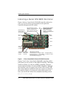
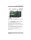
Installing the Hardware
14 3ware 9000 Series Serial ATA RAID Controller Installation Guide
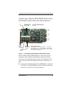
Warning: A common or shared LED ground on a chassis is not
supported and can damage the 3ware controller. Check with your
chassis documentation before connecting.
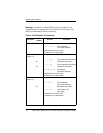
Table 1: LED Indicator Pin Positions
Controller
LED
Header
Pin Pair Comment
9500S-4LP J3 : : : : : Orientation Horizontal
0 1 2 3 All Port number/All
(all activity indicator)
k-cathode-minus is on the top
a-anode-plus is on the bottom
9500S-8
(Pchip v1.4)
J7 : : : : : Orientation Horizontal
0 1 2 3 NU Port number/NU (Not Used)
J8 : : : : : Orientation Horizontal
4 5 6 7 NU Port number/NU (Not Used)
J9 : : : : : Orientation Horizontal
NU NU NU NU All Not used/All
(all activity indicator)
k-cathode-minus is on the top
a-anode-plus is on the bottom
9500S-8
(Pchip v1.5)
J7 : : : : : Orientation Horizontal
0 1 2 3 All Port number/All
(all activity indicator)
J8 : : : : : Orientation Horizontal
4 5 6 7 NU Port number / NU
(Not Used)
k-cathode-minus is on the top
a-anode-plus is on the bottom