


Installing a Serial ATA RAID Controller
www.3ware.com 15
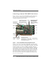
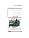
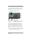
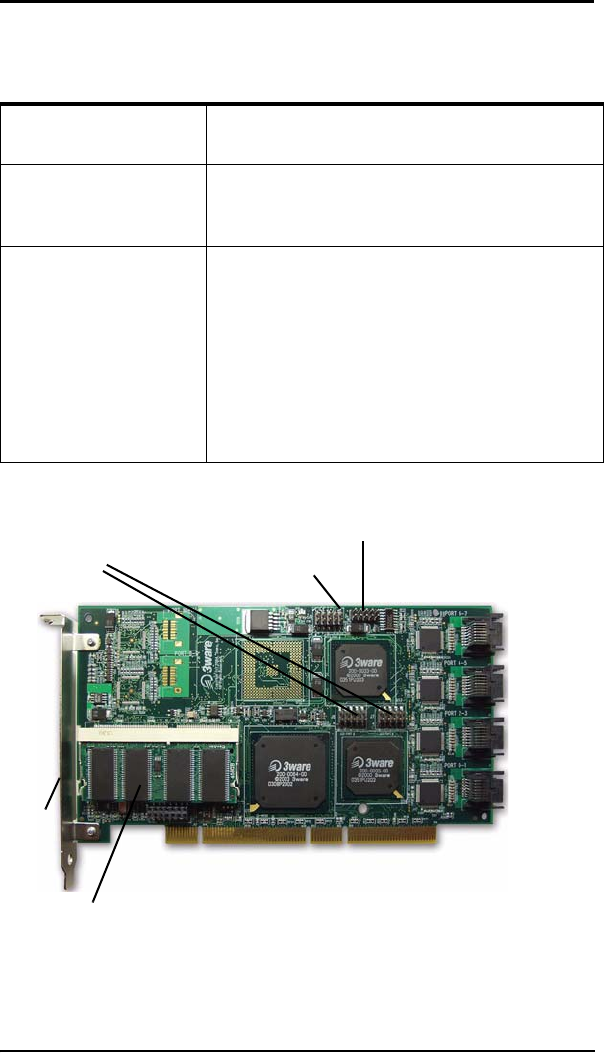
Figure 3. 8-Port 3ware 9500S-8 Serial ATA RAID Controller, Pchip
v1.4 (Non-BBU Compatible)
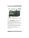
9500S-12 J7 : : : : : Orientation Horizontal
0 1 2 3 NU Port number/NU (Not Used)
J8 : : : : : Orientation Horizontal
4 5 6 7 NU Port number/NU (Not
Used)
J9 : : : : : Orientation Horizontal
8 9 10 11 All Port number/All (all activity
indicator)
k-cathode-minus is on the top
a-anode-plus is on the bottom
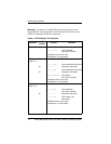
Table 1: LED Indicator Pin Positions
Controller
LED
Header
Pin Pair Comment
LED indicators
for individual
drives on J7
and J8
Overall LED drive status
indicator: the last two pins
of J9. The anode is the
lower of the two pins and
the cathode is the upper.
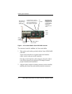
Serial
number
(on plate)
Ports:
6 and 7
4 and 5
2 and 3
0 and 1
Serial ports are double-
stacked connectors.
Odd-numbered ports 1
through 7 are located
below even-numbered
ports 0 through 6.
SODIMM (memory
module)
I
2
C
connector
LED connector details
J7 is for drives 0, 1, 2, 3 (left to right)
J8 is for drives 4, 5, 6, 7 (left to right)
The last two pins on
J7 and J8 are unused.