


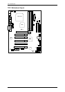
7ZX-1 Motherboard
11
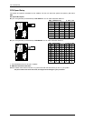
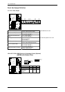
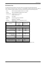
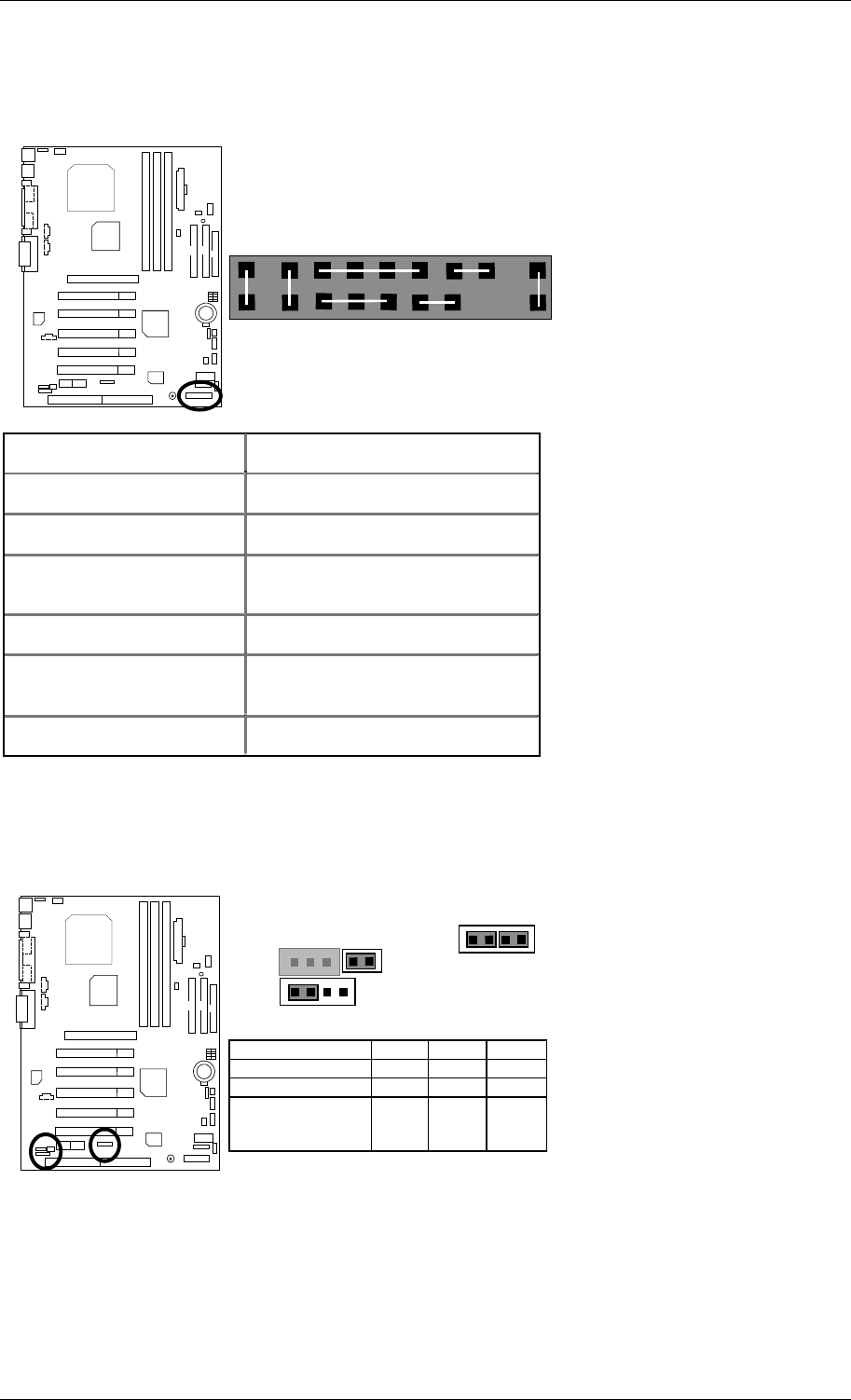
Panel And Jumper Definition
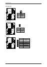
J11: 2x11 Pins Jumper
RE
GN
GD
PW
P−P−P+
S P K
HD
1
1
1
1
GN (Green Switch) Open: Normal Operation
Close: Entering Green Mode
GD (Green LED) Pin 1: LED anode(+)
Pin 2: LED cathode(−)
Not available at the case
HD (IDE Hard Disk Active
LED)
Pin 1: LED anode(+)
Pin 2: LED cathode(−)
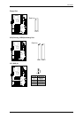
SPK (Speaker Connector) Pin 1: VCC(+)
Pin 2- Pin 3: NC
Pin 4: Data(−)
For external speaker in the case
RE (Reset Switch) Open: Normal Operation
Close: Reset Hardware System
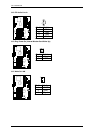
P+P−P−(Power LED)
Pin 1: LED anode(+)
Pin 2: LED cathode(−)
Pin 3: LED cathode(−)
PW (Soft Power Connector) Open: Normal Operation
Close: Power On/Off
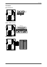
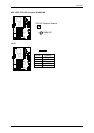
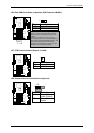
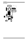
JP16 /JP17/JP18: AMR (Primary or Secondary) Select (Optional)
(AMR
Audio Modem Riser)
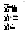
JP16 JP17 JP18
Onboard AC97 ON 1-2 1-2
AMR (Primary) OFF 3-4 3-4
Onboard AC97+MR
(Secondary)
(Default)
ON 1-2
3-4
1-2
1
JP17
1
JP16
1
JP18