


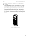

MX28B-1200+27V PRODUCT MANUAL Rev 1
8
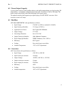
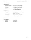
4.5 Control Unit
The microprocessor-based power system control unit is 1U high (1.75”) and provides control and
monitoring functions. Features implemented are:
• 32-character alphanumeric display (2 lines by 16 characters)
• LED alarm and status indicators
• Standard voltage and battery charging control
• Battery temperature compensation (optional temperature probe)
• Monitoring of up to 6 shelves of four rectifiers each and up to 8 DC to DC Converters
• Individual alarm monitoring of 72 breakers
• Individual alarm monitoring of 16 power distribution fuses
• Eight alarm / annunciation relays (Major, Minor, and six user defined) with form C contact
outputs
• Four external alarm inputs (either N.O. or N.C. contacts)
• Control for two independent Low Voltage Disconnects (LVD’s)
• WEB/SNMP Interface Card for remote monitoring
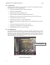
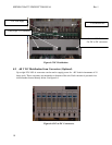
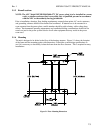
4.6 AC Input Power
Each rectifier shelf requires 208/220/240V ac, single-phase, 50/60 Hz, supplied through an external
80-amp breaker. Three Vertical wire conduits in the left rear of the frame provide routing for AC
input power connection of each shelf. The Earth Ground wiring is factory installed to each rectifier
shelf. A power entry box with 3 pilot holes is provided at the top and rear of the frame where AC
wiring conduit can be run. Refer to Figure 4-3.
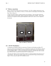
Figure 4.3 Power Entry Box
AC wire conduits (3)