


Rev 1 MX28B-1200+27V PRODUCT MANUAL
21
5.8.2 Installation of Circuit Breakers
1) Remove the metal circuit breaker cover panels.
2) Use diagonal cutters to cut the metal web of the breaker panel “knock-outs” at the desired
breaker locations.
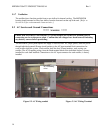
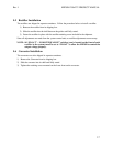
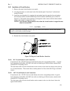
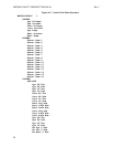
3) Install the circuit breaker(s) by snapping the top terminal onto the upper bus bar and rotating
the unit down until the second terminal snaps onto the breaker termination post as shown in
Figure 5-8. The breaker alarm terminals are designed to make contact with the alarm terminal
board as the breaker is snapped into place.
NOTE: Circuit breaker alarm contacts close when the circuit breaker is tripped but not
when it is turned OFF.
***** CAUTION *****
During circuit breaker installation, carefully align the breaker alarm terminals with the alarm terminal
board to avoid breaker terminal damage.
4) Reattach the circuit breaker cover panels.
Figure 5-8 Plug-in Circuit Breaker Insertion
5.8.2.1 24V Circuit Breaker Load Connections
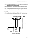
Connections for the +24V DC loads are located directly above the corresponding breaker. A typical
load connection would utilize a #6 AWG wire with a two-hole lug on 5/8-inch centers, attached with
standard #10-32 mounting screws.
The load return cables for each circuit breaker section connect to the return bus directly above the top
row of circuit breakers. These return buses contain patterns for 40 two-hole #10-32 lugs on 5/8-inch
centers.
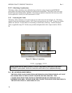
5.8.2.2 –48V Circuit Breaker Load Connections
Connections for the –48V DC loads are made directly above the corresponding breaker. A typical
load connection would utilize a #6 AWG wire with a two-hole lug on 5/8-inch centers, attached with
standard #10-32 mounting screws.
The load return cables for each circuit breaker section connect to the return bus located above the
upper circuit breakers.