


11 990-1060B 12/2005
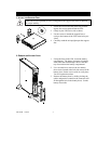
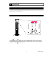
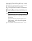
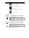
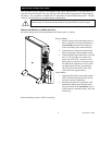
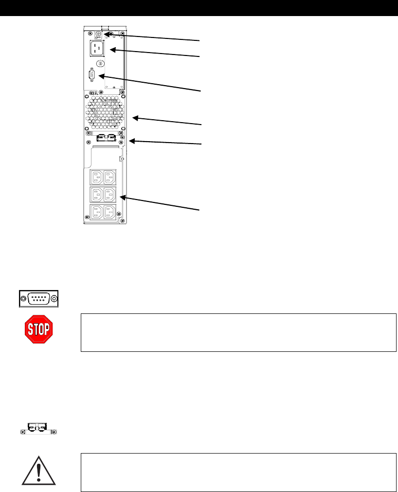
REAR PANEL
TVSS Ground
Input Plug
Computer Interface Port
Fan
External Battery Connector Port
Outlets
B
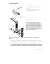
ASIC CONNECTORS
Computer Inter-
face Port
Power management software and interface kits can be used with the UPS.
Use only interface kits supplied or approved by APC. If used, connect the
interface cable to the 9-pin computer interface port. Secure the connector
screws to complete the connection.
Use the APC supplied cable to connect to the Computer Interface Port.
DO NOT use a standard serial interface cable since it is incompatible
with the UPS connector.
TVSS Screw
The UPS features a transient voltage surge-suppression (TVSS) screw for
connecting the ground lead on surge suppression devices such as telephone
and network line protectors.
External Battery
Connector Port
External battery packs can be obtained to connect to your UPS and give
longer runtime during power outages. If used, unscrew the protective plate
from in front of the connector port and insert the cable supplied with the bat-
tery pack into the connector port. Battery Packs can be daisy chained to-
gether to achieve desired run time.
To connect optional external battery pack(s) to the UPS, refer to the Smart-
UPS RT Battery Pack User’s Manual for instructions. This Smart-UPS RT
XL can support a maximum of ten external battery packs.
Input
Circuit Breaker
If the plunger on the circuit breaker pops out, reduce the load on the UPS by
unplugging equipment and press the plunger in.