


990-1007A, Revision 2 9/99 12
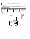
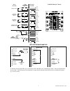
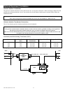
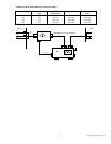
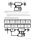
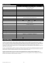
Standard System With Isolating Transformer (400 V) And SBP
System Mains Fuse*
(Fm)
Input Cable
Transformer
Input Cable UPS Output Cable
UPS
4kV 16A 3x2.5mm² 3x6mm² 3x6 mm²
6kV 25A 3x6 mm² 3x16 mm² 3x10 mm²
8kV 32A 3x10 mm² 3x16 mm² 3x10 mm²
10kV 40A 3x10 mm² 3x16 mm² 3x16 mm²
*Din gl Types
System Output Cable UPS Output Fuse SBP (Fo) Output Cable SBP
4kV 3x4 mm² 20A 3x4 mm²
6kV 3x10 mm² 32A 3x10 mm²
8kV 3x10 mm² 40A 3x10 mm²
10kV 3x16 mm² 50A 3x16 mm²
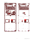
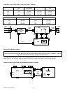
LOADMAINS
L1
L2
PE
Input
Cable Tr.
Iso.Tr
.
L1
L2
Tr. Sw. cable
L
N
UPS
NL NL
INPUT
CABLE
SBP
L
N
OUTPUT
CABLE
SBP
SBP
L
N
L
N
Input
cable
UPS
Output
cable
UPS
Fm
Fo
Fm
1 2 3 4
MBS CONTROL
SBP
CABLE
X010
1 2 3 4
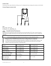
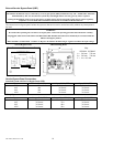
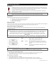
External Run Battery Cabinet
Note:
You must attach a ferrite bead to the signal cable of the extended run battery cabinet to ensure regulatory compliance. A ferrite
bead and its installation instructions are included in the literature kit.
For longer uninterrupted power during UPS on-battery operation, connect an extended run battery cabinet to the
Smart-UPS DP. All connection diagrams show the UPS with an extended run battery cabinet already connected.
Detail of Smart-UPS DP with an Extended Run Battery Cabinet
UPS
EPOCOM
PORT
NL NL
DC
384V
Belt
Temp.
sensor
++
DC
cable
Temp.
sensor
cable
Ext.
DC
Ext.
Batt
Temp.
UPS
output
UPS
input
MBS control
Ext. Tr.
Th.
Sw.