


Configuration Menu AM64/128A User Manual
34
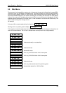
5.7.3 X.21 Loop Control
This facility is designed for when a pair of BBM’s are used as an extension to another BBM link.
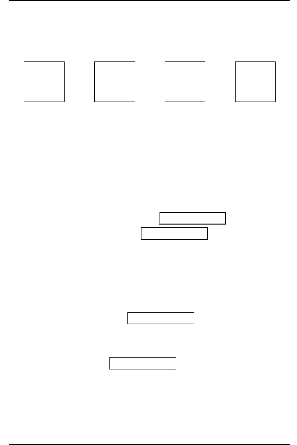
The concept is shown below.
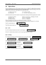
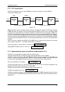
Figure 5.7.3
BBM’s A and B form part of a conventional link. However in this example, instead of a DTE being connected
to BBM B another link is started. This link extension starts with BBM C, which is in turn connected to BBM
D (or even a line card feeding into a network). Details of the second link are not important. If BBM A (or
the DTE it is connected to) attempts to apply a remote loop, it would normally be applied at B. However,
if the X.21 loops off option is applied at B, then the remote loop command will travel through to BBM D.
The remote loop has thus been applied at the very far end of the network. The option effectively tells BBM
B to ignore any loop requests from the line. Any internally activated loops (i.e. from the front panel) behave
as before.
Note: if this option is applied the RX NRDY LED in BBM B will not function as all the data is now treated
as structured (no status line - ‘Not Ready’ patterns have no meaning).
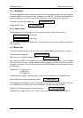
The normal ‘loops on’ mode is shown in the menu as: C > X21 Loops On
Pressing SELECT enables ‘loops off’, shown as: C > X21 Loops Off
5.7.4 Synchronisation Type (for software versions below V1.3)
This option is only applicable to master mode with external timing.
This option allows the user to change the type of clock synchronisation within the BBM.
Normally in a point to point link, the master BBM becomes the source of timing and the slave BBM locks
to this. If a further link is driven as shown in figure 5.7.3, then the external BBM C must supply a source
of timing to the master BBM B. This timing can be of two forms Bit Timing, or Byte Timing.
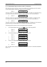
Bit timing is selected with the display C > Bit Sync
The Bit timing signal must be of the same frequency as the user bit rate. The circuitry is designed to be
supplied with the timing clock output from an other BBM.
The signal connections are via the interface connectors, (see appendix A).
The Byte timing signal is shown by C > Byte Sync
The Byte timing signal must be a half wide pulse every 8 data bits. The BBM is designed to accept the byte
timing output from a slave BBM operating at 64kb/sec. Signal connections are via the interface connectors
(Appendix A).
slave master
Modem
A
Modem
B
Modem
C
Modem
D
To DTE X2.1 Link To DTE
Normal BBM to BBM link External link or network