


Appendix A - Interface Connections AM64/128A User Manual
A-2
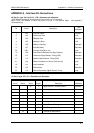
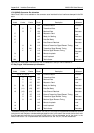
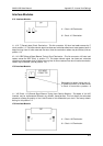
V.35 (MRAC) Connector Pin allocation
Note: Circuit 108/1 is not available on the connector as an interface line but is software clamped in the ON
state.
Pin
Unbal
B
C
D
E
F
N
L
NN*
Description
Common Return
Transmitted Data
Received Data
Request to Send
Ready for Sending
Data Set Ready
Data Channel Received
External Transmitter Signal Element Timing
Transmitter Signal Element Timing
Receiver Signal Element Timing
Remote Loopback
Local Loopback
Test Indicator
A wire
P
R
U
Y
V
B wire
S
T
W
AA*
X
Circuit
102
103
104
105
106
107
109
113
114
115
140
141
142
TYPE
SITS 89/43
Common
Load
Generator
Load
Generator
Generator
Generator
Load
Generator
Generator
Load
Load
Generator
Pin
19, 20, 27, 29, 31
Unbal
9
11
13
14
10
18
Description
Common Return
Transmitted Data
Received Data
Request to Send
Ready for Sending
Data Set Ready
Data Channel Received
External Transmitter Signal Element Timing
Transmitter Signal Element Timing
Receiver Signal Element Timing
Remote Loopback
Local Loopback
Test Indicator
A wire
4
6
7
(9)
(11)
(13)
17
5
8
B wire
22
24
25
(27)
(29)
(31)
35
23
26
Circuit
102
103
104
105*
106*
107*
109*
113
114
115
140
141
142
TYPE
SITS 89/43
Common
Load
Generator
Load
Generator
Generator
Generator
Load
Generator
Generator
Load
Load
Generator
Note that on some MRAC connectors pin ‘AA’ is marked as ‘a’ and pin ‘NN’ is marked ‘m’.
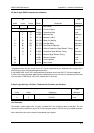
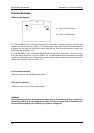
37 Way D-type V.36 Connector pin allocation
*Standards indicate that the control circuits 105,106,107,109 may be implemented as balanced circuits
(using both A and B wires) or unbalanced single ended circuits. In the case of the control circuits the A wire
is to be used and the B wire is to be joined to GND (circuit 102) at the receiver end of the circuit. In the
AM64/128A circuit 105 is implemented as a balanced circuit and 106,107,109 are unbalanced.