


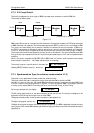
AM64/128A User Manual Appendix A - Interface Connections
A-3
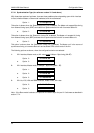
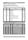
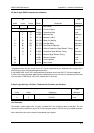
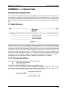
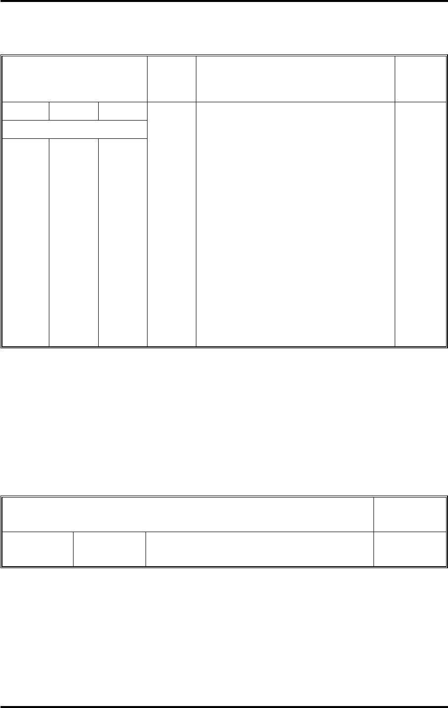
25 Way D-type RS-530 Connector pin allocation
*Standards dictate that the control circuit 107 may be implemented as a balanced circuit (using both A
and B wires) or as an unbalanced single ended circuit.
In the AM64/128A, circuit 105 is implemented as a balanced circuit and 106,107,109 are unbalanced.
To allow inter working between balanced and unbalanced circuits, the A wire is to be used and the B wire
is to be joined to GND (circuit 102) at the receiver end of the circuit.
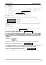
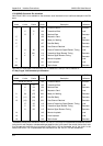
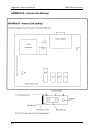
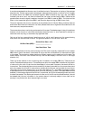
9 Way D-type (64 kbps, 120 Ohm) Codirectional Connector pin allocation
Line Connector
The modem comes packed with a 6-way, 4-loaded RJ11 line connector cable as standard. The line
connections are the middle two pins (2 & 3, blue and green wires) in the RJ11 6-way, 4-loaded connector.
Note: Alternative Line cord connectors are available upon request.
Pin
Unbal
1
7, 22, 10, 13
5
6
8
21
18
25
2
3
4
(5)
(6)
(8)
25
15
17
14
16
19
(13)
(22)
(10)
11
12
9
103(AB)
103(BA)
104(BB)
105*(CA)
106*(CB)
107*(CC)
109*(CF)
113(DA)
114(DB)
115(DD)
140(RL)
141(LL)
142(TM)
Earth/Shield
Common Return
Transmitted Data
Received Data
Request to Send
Ready for Sending
Data Set Ready
Data Channel Received
External Transmitter Signal Element Timing
Transmitter Signal Element Timing
Receiver Signal Element Timing
Remote Loopback
Local Loopback
Test Indicator
Common
Common
Load
Generator
Load
Generator
Generator
Generator
Load
Generator
Generator
Load
Load
Generator
A wire B wire Circuit Description
SITS 89/43
TYPE
A wire
1
6
5
9
G.703 OUT
G.703 IN
Generator
Load
B wire Description
SITS 89/43
TYPE