


AM64/128A User Manual Appendix A - Interface Connections
A-1
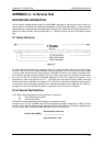
APPENDIX A - Interface Pin Connections
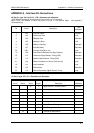
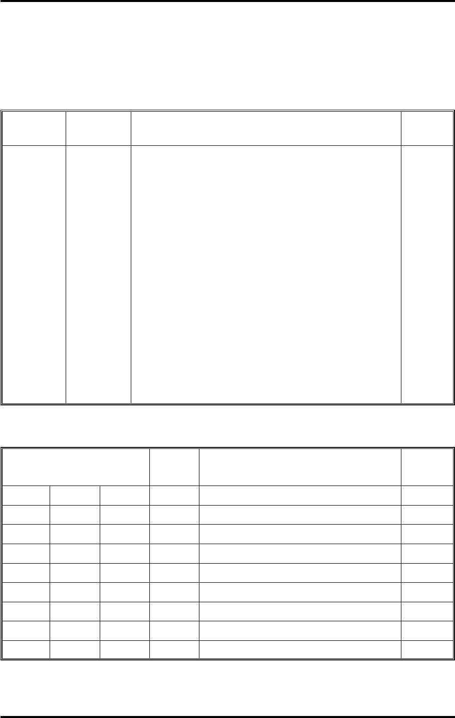
25 Way D - type X.21 bis (V.24 / V.28*) Connector pin allocation
*V.28 defines the electrical characteristics of the circuits of a V.24 interface.
Note: Circuit 105 Request to send may have to be set in the Options Menu - see Appendix F
(Troubleshooting).
7
2
3
4
5
6
20
8
15
17
21
18
25
24
102
103
104
105
106
107
108.1
109
114
115
140
141
142
113
Description
Common Return
Transmitted Data
Received Data
Request to Send
Ready for Sending
Data Set Ready
Connect Data Set to Line
Data Channel Received Line Signal Detector
Transmitter Signal Element Timing (DCE)
Receiver Signal Element Timing (DCE)
Remote Loopback for Point-to-Point circuits
Local Loopback
Test Indicator
External Transmitter Signal Element Timing
TYPE
SITS 89/43
Common
Load
Generator
Load
Generator
Generator
Load
Generator
Generator
Generator
Load
Load
Generator
Load
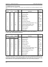
15 Way D-type X.21 (V.11) Connector pin allocation
Pin Circuit
Pin
A wire
15
2
4
3
5
6
7
7
Description
Signal Ground / Common Return
External Signal element Timing
Transmit
Received
Control
Indication
Signal Element Timing
Byte Timing
Frame Start Identification
B wire
1
9
11
10
12
13
14
14
Unbal
8
Circuit
G
S EXT
T
R
C
I
S
B
F
TYPE
SITS 89/43
Common
Generator
Load
Generator
Load
Generator
Generator
Generator
Generator