


17
6.0 RIBBON
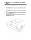
When thermal transfer is selected as print media type, the following adjustment should be
made in accordance with ribbon running condition. If you have repositioned the thermal
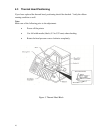
head, it is highly recommended to adjust the ribbon.
6.1 Ribbon Adjustment
To understand ribbon adjustment better, refer to the following explanation.
Ribbon running condition is directly related to the condition of the following
components:
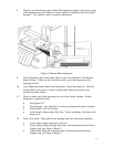
• Ribbon supply shaft with friction brake. Ribbon roll is loaded to this shaft.
The friction brake is provided to eliminate looseness from ribbon.
• Leading shaft to change ribbon running direction.
• Heat lines of thermal head and platen roller.
• Bottom front edge of thermal head.
• Bottom edge and surface of ribbon applicator to change ribbon running
direction.
• Ribbon take-up shaft. Take-up core is set on this shaft in order to wind
waste ribbon. Take-up motor powers this shaft.
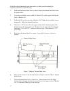
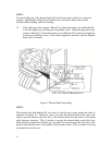
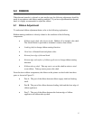
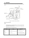
From the above ribbon components, the ribbon on the printer can be divided into three
parts as shown in Figure 12:
• Part A: The part of the ribbon between ribbon supply shaft and leading
shaft.
• Part B: The part of the ribbon between leading shaft and the front edge of
ribbon applicator.
• Part C: The part of the ribbon between the bottom edge of ribbon
applicator and ribbon take-up shaft.