


Table of Contents
1.0 GENERAL INFORMATION...........................................................................................................................1
1.1 Features............................................................................................................................................................1
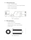
1.2 5106 Overall Dimensions.............................................................................................................................2
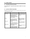
1.3 Ribbon Specifications...................................................................................................................................2
2.0 INITIAL SETUP.................................................................................................................................................3
2.1 Assembly and Setup Procedure ...................................................................................................................3
2.2 Selection of Media Output Mode................................................................................................................3
2.3 Parameter Setting Mode................................................................................................................................4
2.4 Parameter Tree Version 1.90........................................................................................................................5
3.0 LOADING INK RIBBON AND LABEL ROLL..........................................................................................6
4.0 ADJUSTMENTS................................................................................................................................................8
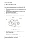
4.1 Thermal Head Replacement.........................................................................................................................8
4.2 Changing the Direction of the Take-up Roller..........................................................................................9
4.3 Thermal Head Positioning..........................................................................................................................10
5.0 MECHANICAL ADJUSTMENTS TO THE THERMAL HEAD..........................................................11
6.0 RIBBON.............................................................................................................................................................17
6.1 Ribbon Adjustment......................................................................................................................................17
6.2 Running Condition.......................................................................................................................................19
7.0 SENSORS..........................................................................................................................................................21
8.0 SENSITIVITY ADJUSTMENT....................................................................................................................22
9.0 ELECTRICAL CIRCUITRY..........................................................................................................................24
10.0 EXTERNAL CONNECTOR AND PIN ASSIGNMENTS.......................................................................25
11.0 VOLTAGE CHECK AND ADJUSTMENT...............................................................................................26
12.0 MAIN PCB BOARD........................................................................................................................................27
13.0 TAKE-UP MOTOR CONNECTORS...........................................................................................................28
Table of Figures
Figure 1. Overall Dimensions........................................................................................................................................2
Figure 2. Ribbon Dimensions........................................................................................................................................2
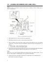
Figure 3: Loading Ribbon and Label Roll...................................................................................................................6
Figure 4. Thermal Head Replacement..........................................................................................................................8
Figure 5. Thermal Head Block.....................................................................................................................................10
Figure 6. Mechanical Adjustment...............................................................................................................................11
Figure 7. Hinge of Thermal Head Lever....................................................................................................................12
Figure 8. Thermal Head Alignment............................................................................................................................13
Figure 9. Thermal Head Positioning...........................................................................................................................14
Figure 10. Head Positioning.........................................................................................................................................15
Figure 11. Incline Checking of the Thermal Head...................................................................................................16
Figure 12. Ribbon Running Condition.......................................................................................................................18
Figure 13. Wrinkle On Ribbon....................................................................................................................................19
Figure 14. Ribbon Application Adjustment..............................................................................................................20
Figure 15. Location of Sensors and Switch...............................................................................................................21