


Connections and Wiring
20
NetLinx Integrated Controllers
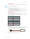
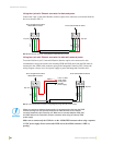
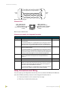
Using the 4-pin mini-Phoenix connector for data and power
Connect the 4-pin 3.5 mm mini-Phoenix (female) captive-wire connector to an external NetLinx
device as shown in FIG. 8.
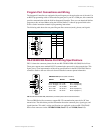
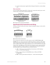
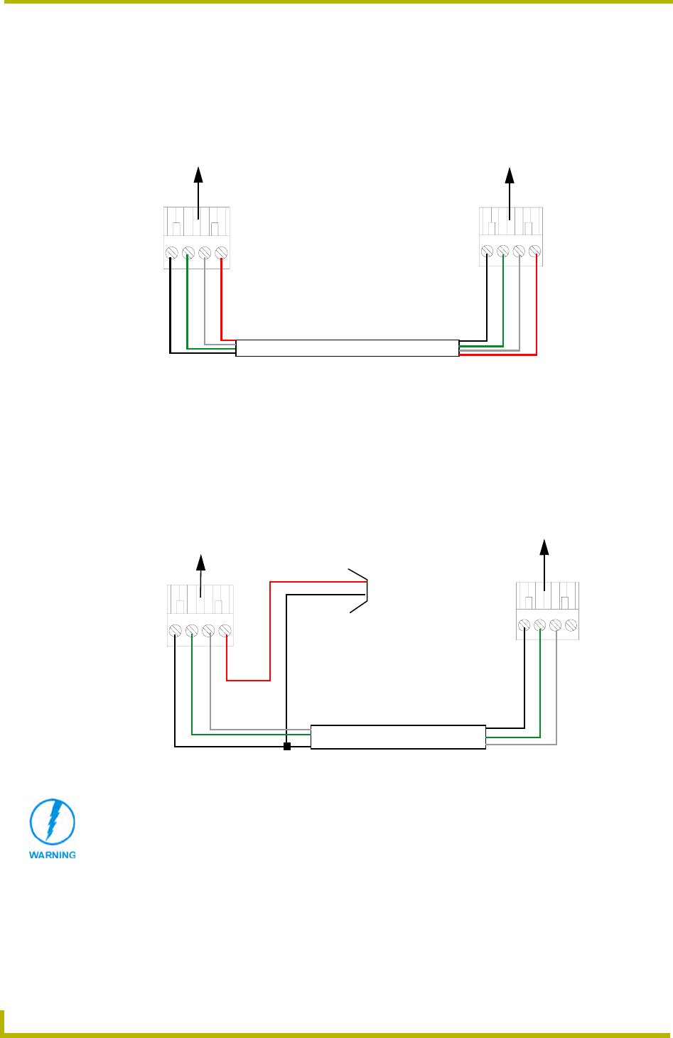
Using the 4-pin mini-Phoenix connector for data with external power
To use the NetLinx 4-pin 3.5 mm mini-Phoenix (female) captive-wire connector for data
communication and power transfer, the incoming PWR and GND cable from the PSN must be
connected to the AXlink cable connector going to the Integrated Controller. FIG. 9 shows the
wiring diagram. Always use a local power supply to power the Integrated Controller unit.
Make sure to connect only the GND wire on the AXlink/PWR connector when using a separate
12 VDC power supply. Do not connect the PWR wire to the AXlink connector’s PWR (+)
opening.
FIG. 8 Mini-Phoenix connector wiring diagram (direct data and power)
FIG. 9 4-pin mini-Phoenix connector wiring diagram (using external power source)
To the Integrated Controller’s
To the external NetLinx device
AXlink/PWR connector
PWR +
AXP/TX
AXM/RX
GND -
Top view
Top view
PWR +
AXP/TX
AXM/RX
GND -
PWR (+)
GND (-)
Local +12 VDC
(coming from
To the Integrated Controller’s
To the external NetLinx device
AXlink/PWR connector
power supply
the PSN
power supply)
Top view
Top view
AXP/TX
AXM/RX
GND -
AXP/TX
AXM/RX
GND -
When you connect an external power supply, do not connect the wire from the PWR
terminal (coming from the external device) to the PWR terminal on the Phoenix
connector attached to the Controller unit. Make sure to connect only the AXM, AXP,
and GND wires to the Controller’s Phoenix connector when using an external PSN
power supply.