


Introduction
6
NI-700 & NI-900 Hardware Reference Guide
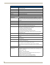
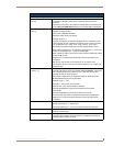
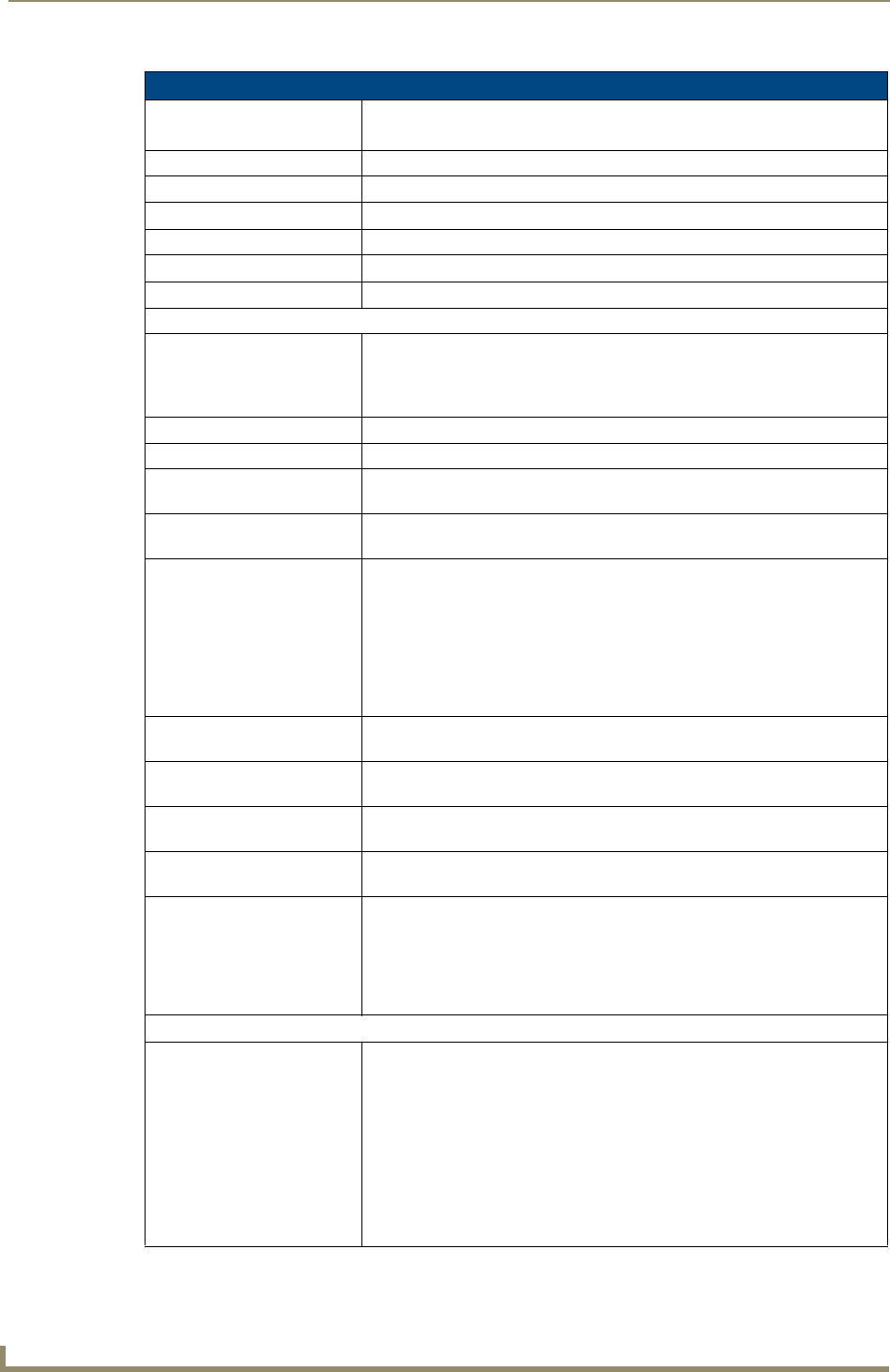
NI-900 Specifications
Dimensions (HWD): • 1.58" x 5.54" x 5.12" (4.01 cm x 14.10 cm x 13.00 cm)
• 1 RU (rack unit) high
Power Requirements: • 300 mA @ 12 VDC
Memory: See the NI-900 On-Board Memory Specifications section on page 9.
Microprocessor: • 304 MIPS
Weight: • 1.30 lbs (0.59 kg)
Enclosure: • Metal with black matte finish
Certifications: • FCC Part 15 Class B, CE, and IEC 60950
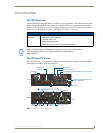
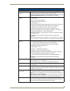
Front Panel Components:
Program port • RS-232 DB9 connector (male) can be connected to a DB9 port on a
computer. This port can be used with both Serial and NetLinx programming
commands. It is also used to both upload and download information from
the NetLinx Studio 2.4 program.
Configuration DIP switch • Sets the communication parameters for the Program port.
IR RX LED • Red LED lights to when IR data is being received via the rear IR RX port.
IR LEDs • Three red LEDs light during the transmission of IR or Serial data via the rear
IR port.
I/O LEDs • Four yellow LEDs light when the rear I/O channels 1 - 4 are active. LED
indicator for each I/O port reflects the state of that particular port.
Serial LEDs • One set of red and yellow LEDs light when the rear DB9 Port (1) transmits or
receives RS-232, 422, or 485 data:
- TX LED (red) lights when transmitting data
- RX LED (yellow) lights when receiving data
- LED activity reflects transmission and reception activity
• These LEDs do not reflect changes in either the RTS or CTS when
hardware handshaking is used.
LINK/ACT • Green LED lights when the Ethernet cable is connected and an active link is
established. This LED also blinks when receiving Ethernet data packets.
Status • Green LED lights when the Controller is programmed and communicating
properly.
Output • Red LED lights when the Controller transmits data, sets channels On/Off,
sends data strings, etc.
Input • Yellow LED lights when the Controller receives data from button pushes,
strings, commands, channel levels, etc.
ID pushbutton Provides the NetLinx ID (D:S) assignment for the device.
• The D notation is used to represent a device number.
• The S notation is used to represent the System number of the Master.
• Refer to the NetLinx Integrated Controller WebConsole & Programming
Guide for details.
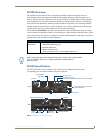
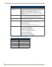
Rear Panel Components:
RS-232/422/485
(Port 1)
• RS-232/422/485 control port uses a DB9 (male) connector with
XON/XOFF (transmit On/transmit Off), CTS/RTS (clear to send/ready to
send), and 300 - 115,200 baud.
• Channel range = 1 - 255
• Channels 1 - 254 provide feedback
• Channel 255 (CTS Push channel): Reflects the state of the CTS Input if a
'CTSPSH' command was sent to the port
• Output data format for each port is selected via software
• A single DB9 connector provides RS-232/422/485 termination