


Introduction
7
NI-700 & NI-900 Hardware Reference Guide
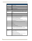
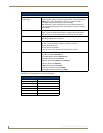
NI-900 Specifications (Cont.)
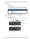
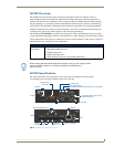
Rear Panel Components (Cont.):
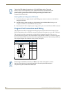
IR RX
(Port 6)
• 4-pin 3.5 mm mini-Phoenix port is used to connect one or more
(8 maximum) IRX-SM+ swivel mount or IRX-DM+ Decora mount IR
receivers.
• The IR RX port functions using AMX IR codes (38 KHz and 455 KHz) and
works ONLY with AMX IR Receivers such as the IRX-DM+ and IRX-SM+.
Digital I/O
(Port 5)
• Four-channel binary I/O port for contact closure with each input being
capable of voltage sensing.
• Input format is software selectable.
• Interactive power sensing for IR ports
• Channel range = 1 - 4
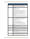
• All inputs are assigned to respective IR/Serial ports for "automatic" power
control through the use of software commands. Power control is provided
via commands such as: ’PON’, ’POF’, ’POD’, ’DELAY’, I/O Link etc.).
• Contact closure between GND and an I/O port is detected as a PUSH
• When used as voltage input - I/O port detects a low signal (0 - 1.5 VDC) as a
PUSH and a high signal (3.5 - 5 VDC) as a RELEASE
• When used as an output - each I/O port acts as a switch to GND and is rated
at 200 mA @ 12 VDC
• Single 6-pin 3.5 mm mini-Phoenix (female) connector provides I/O port
termination
Note: This IO uses 5V logic but can handle up to 12V without harm.
It can handle up to 12V on the input. At higher voltages you run a higher risk
of surge damage.
IR/Serial
(Ports 2 - 4)
• This multi-port (containing three sets of IR connectors) is capable of
generating IR with the use of an IR Emitter (while in IR mode). These ports
can support high-frequency carriers of up to 1.142 MHz and can also
generate IR with no carrier frequency.
• Each output is capable of three electrical formats: IR, Serial, and Data
• Multiple IR/Serial signals can be generated.
• Channel range = 1 - 255
• Channels 1 - 128 (output): IR commands
• Channels 129 - 253: used as reference channels
• Channel 254 (feedback): Power Fail (used with 'PON' and 'POF'
commands)
• Channel 255 (feedback): Power status (when IO Link is set)
• IR ports support data mode (at limited baud rates and wiring distances).
• Single 2-pin 3.5 mm mini-Phoenix (female) connector provides IR port
termination
AXlink LED • Green LED indicates the state of the AXlink connector port.
• Normal AXlink activity = 1 blink/second
• Abnormal AXlink activity = cycle of 3 consecutive blinks and then Off
AXlink port • 4-pin 3.5 mm mini-Phoenix (male) connector provides data and power to
external control devices.
Ethernet port • RJ-45 port for 10/100 Mbps communication. The Ethernet Port automatically
negotiates the connection speed (10 Mbps or 100 Mbps) and whether to
use half duplex or full duplex mode.