


Connections and Wiring
18
NI-700 & NI-900 Hardware Reference Guide
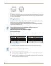
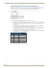
Using the 4-pin Mini-Phoenix Connector For Data With External Power
To use the 4-pin 3.5 mm mini-Phoenix (female) captive-wire connector for data communication and
power transfer, the incoming PWR and GND cable from the 12 VDC-compliant power supply must be
connected to the AXlink cable connector going to the Integrated Controller. FIG. 4 shows the wiring
diagram. Always use a local power supply to power the Integrated Controller unit.
Make sure to connect only the GND wire on the AXlink/PWR connector when using a separate 12 VDC
power supply. Do not connect the PWR wire to the AXlink connector’s PWR (+) opening.
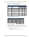
DB9 Device Port: Connections and Wiring
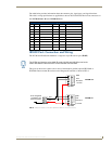
FIG. 5 shows the connector pinouts for the rear RS-232/RS-422/RS-485 (DB9) Device Ports.
The NI-700 has two ports whereas the NI-900 only has one available DB9 Device Port.
These ports support most standard RS-232 communication protocols for data transmission. This figure
gives a visual representation of the wiring specifications for the RS-232/422/485 Device connectors.
Refer to the rear of the unit for more detailed connector pinout information.
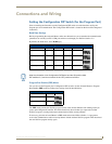
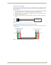
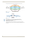
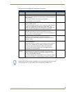
FIG. 4 4-pin mini-Phoenix connector wiring diagram (using external power source)
PWR (+)
GND (-)
Local +12 VDC
(coming from
To the Integrated Controller’s
To the external AXlink device
AXlink/PWR connector
power supply
an external
power supply)
Top view
Top view
AXP/TX
AXM/RX
GND -
AXP/TX
AXM/RX
GND -
When you connect an external power supply, do not connect the wire from the PWR
terminal (coming from the external device) to the PWR terminal on the Phoenix
connector attached to the Controller unit. Make sure to connect only the AXM, AXP,
and GND wires to the Controller’s Phoenix connector when using an external power
supply.
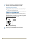
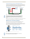
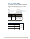
FIG. 5 RS-232/422/485 DB9 (male) connector pinouts for the rear Device Ports
5
4
3
2
1
9
8
7
6
Male
DB9 Serial Port pinouts (male connector)
Pin 2: RX signal
Pin 3: TX signal
Pin 5: GND
Pin 7: RTS
Pin 8: CTS
RS-232
Pin 1: RX -
Pin 4: TX +
Pin 5: GND
Pin 6: RX +
Pin 9: TX -
RS-422
Pin 1: A (strap to 9)
Pin 4: B (strap to 6)
Pin 5: GND
Pin 6: B (strap to 4)
Pin 9: A (strap to 1)
RS-485
While the NI-900 is capable of receiving 8 and 9 bit characters, it cannot receive
7 bit, 1 stop bit data from a serial device (ex: 9600,N,7,1).