


Connections and Wiring
19
NI-700 & NI-900 Hardware Reference Guide
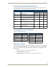
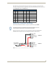
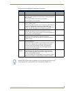
The table below provides information about the connector pins, signal types, and signal functions.
This table’s wiring specifications are applicable to the rear RS-232/422/485 Device Port connectors on
the: NI-700 (Ports 1 & 2) and NI-900 (Port 1).
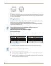
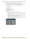
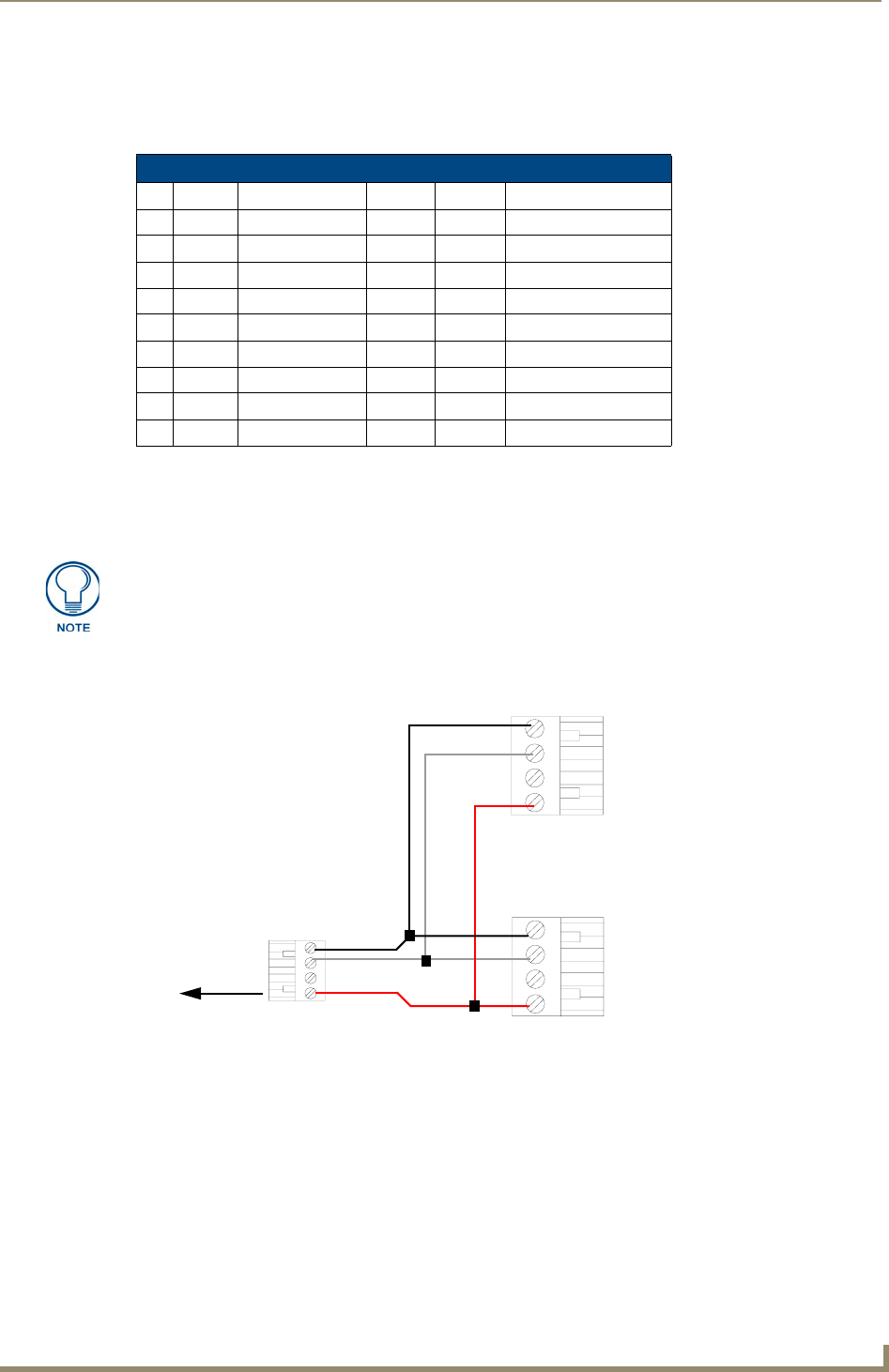
IRX-RX Port: Connection and Wiring
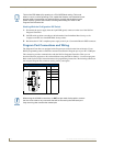
The NI-700 and NI-900 units both have a single rear 4-pin IR receiver port (IR RX).
This port can be used to connect one or more (8 maximum in parallel) optional IRX-SM+ or
IRX-DM+ Decora mount IR receivers to the Integrated Controller as shown in FIG. 6.
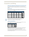
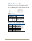
RS-232/422/485 Device Port Wiring Specifications
Pin Signal Function RS-232 RS-422 RS-485
1 RX- Receive data XX (strap to pin 9)
2 RXD Receive data X
3 TXD Transmit data X
4 TX+ Transmit data XX (strap to pin 6)
5 GND Signal ground XX
6 RX+ Receive data XX (strap to pin 4)
7 RTS Request to send X
8 CTS Clear to send X
9 TX- Transmit data XX (strap to pin 1)
The IR RX port functions using AMX IR codes (38 KHz and 455 KHz) and works
ONLY with AMX IR Receivers such as the IRX-DM+ and IRX-SM+.
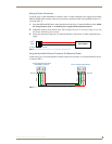
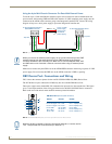
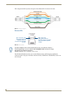
FIG. 6 IR RX port sample connections (AXlink to NetLinx connectors shown)
PWR
GND
IN
AUX
OUT
AUX OUT
+12 VDC
GND
IRX-SM+ #2
IRX-SM+ #1
To the Integrated
Top view
Top view
Top view
OUT
AUX OUT
+12 VDC
GND
Controller’s rear
IR RX connector