


Connections and Wiring
21
NI-700 & NI-900 Hardware Reference Guide
IR/Serial Port: Connections and Wiring
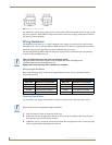
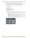
You can connect only one IR- or Serial-controllable device to the IR/Serial connectors on the rear of the
NI-700 (FIG. 8) but you can connect up to three IR- or Serial-controllable devices to the rear of the
NI-900.
These connectors accept an IR Emitter (CC-NIRC) that mounts onto the device's IR window, or a
mini-plug (CC-NSER) that connects to the device's control jack. You can also connect a data 0 - 5 VDC
device. This unit comes with a single CC-NIRC IR Emitter (FG10-000-11).
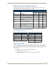
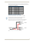
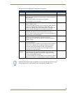
The IR/Serial connector wiring specifications are listed in the following table.
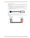
Ethernet/RJ-45 Port: Connections and Wiring
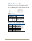
The following table lists the pinouts, signals, and pairing for the Ethernet connector.
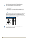
FIG. 8 IR/SERIAL connectors (male)
IR/Serial Connector Wiring Specifications (per Port)
Number of
IR connections
NI-700
Port #
NI-900
Port #
Signal Function
1 3 2 GND (-)
Signal 1 (+)
Signal GND
IR/Serial data
2 N/A 3 GND (-)
Signal 2 (+)
Signal GND
IR/Serial data
3 N/A 4 GND (-)
Signal 3 (+)
Signal GND
IR/Serial data
Ethernet RJ-45 Pinouts and Signals
Pin Signals Connections Pairing Color
1 TX + 1 --------- 1 1 --------- 2 Orange-White
2 TX - 2 --------- 2 Orange
3 RX + 3 --------- 3 3 --------- 6 Green-White
4 no connection 4 --------- 4 Blue
5 no connection 5 --------- 5 Blue-White
6 RX - 6 --------- 6 Green
7 no connection 7 --------- 7 Brown-White
8 no connection 8 --------- 8 Brown
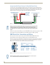
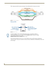
NI-700 IR/Serial connector
configuration (Port 3)
NI-900 IR/Serial connectors
configuration (Ports 2 -4)
123 456 78
123 456 78