


Connections and Wiring
17
NI-700 & NI-900 Hardware Reference Guide
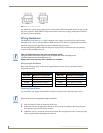
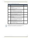
Wiring A Power Connection
To use the 2-pin 3.5 mm mini-Phoenix connector with a 12 VDC-compliant power supply, the incoming
PWR and GND cables from the external source must be connected to their corresponding locations on
connector (FIG. 2).
1. Insert the PWR and GND wires on the terminal end of the 2-pin 3.5 mm mini-Phoenix cable. Match
the wiring locations of the +/- on both the power supply and the terminal connector.
2. Tighten the clamp to secure the two wires. Do not tighten the screws excessively; doing so may strip
the threads and damage the connector.
3. Verify the connection of the 2-pin 3.5 mm mini-Phoenix to the external 12 VDC-compliant power
supply.
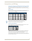
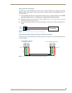
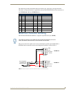
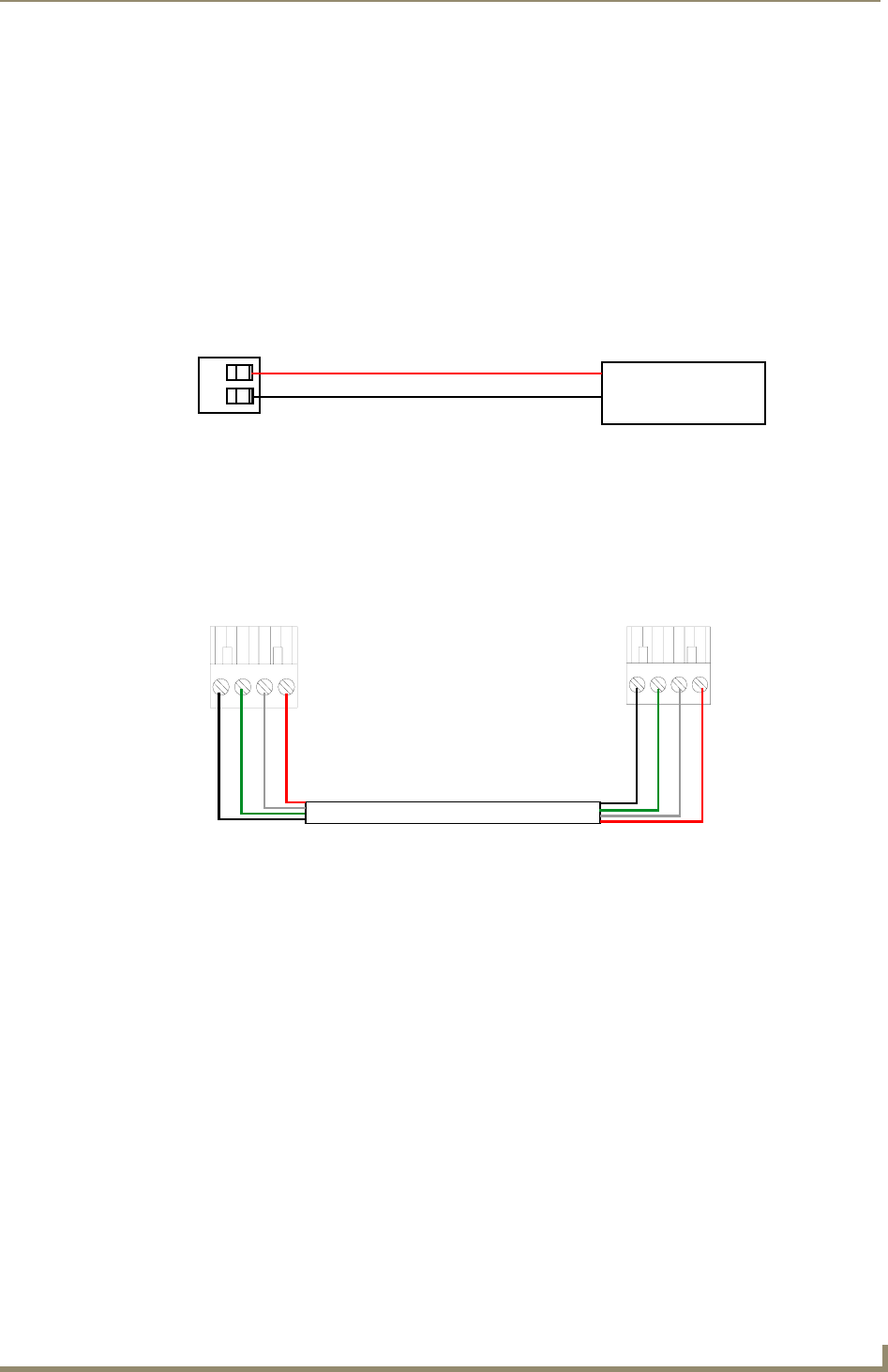
Using the 4-pin Mini-Phoenix Connector For Data and Power
Connect the 4-pin 3.5 mm mini-Phoenix (female) captive-wire connector to an external NetLinx device
as shown in FIG. 3.
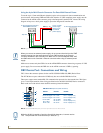
FIG. 2 2-pin mini-Phoenix connector wiring diagram (direct power)
FIG. 3 Mini-Phoenix connector wiring diagram (direct data and power)
PWR +
GND -
To the Integrated Controller
Power Supply
To the Integrated Controller’s
To the external AXlink device
AXlink/PWR connector
PWR +
AXP/TX
AXM/RX
GND -
Top view
Top view
PWR +
AXP/TX
AXM/RX
GND -