


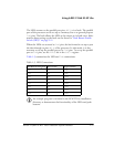
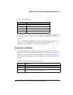

ADSP-21364 EZ-KIT Lite Evaluation System Manual 2-3
ADSP-21364 EZ-KIT Lite Hardware Reference
The
CLKIN pin of the processor connects to a 24.576 MHz oscillator. The
core frequency of the processor is derived by multiplying the frequency at
the CLKIN pin by a value determined by the state of the processor pins,
CLKCFG1 and CLKCFG0. The value at these pins is determined by the state of
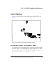
the SW10 switch (see “Boot Mode and Clock Ratio Select Switch (SW10)”
on page 2-12). By default, the EZ-KIT Lite provides a core frequency of
147.456 MHz. It is possible to increase the speed of the processor by
changing the value of the PMCTL register.
The SW10 switch also configures the boot mode of the processor. The
EZ-KIT Lite is capable of parallel port boot and SPI master boot. By
default, the EZ-KIT Lite boots from the parallel port. For information
about configuring the boot modes, see “Boot Mode and Clock Ratio
Select Switch (SW10)” on page 2-12.
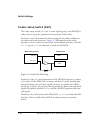
Parallel Port
The parallel port (PP) of the ADSP-21364 processor consists of a 16-bit
multiplex address/data memory bus (AD15–0) and an address latch-enable
pin (ALE). The interface does not have any memory select pins; these sig-
nals must be generated by decoding the address.
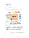
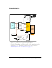
The PP connections to the EZ-KIT Lite are shown in Figure 2-2. The PP
connects to an 8-bit parallel flash memory, an 8-bit SRAM memory, and
eight general-purpose LEDs. The upper three address bits connect to a
3-to-8 decoder, providing eight memory select pins. See “External Mem-
ory” on page 1-7 for more information about accessing the flash and
SDRAM memories.
Because the PP is a multiplexed address/data memory bus, two 8-bit
latches are used to latch the upper address bits. Additional latch is used to
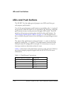
drive the LEDs. The latter allows the LED values to be written to as if
they were at a memory location. For more information about using the
LEDs, refer to the “LEDs and Push Buttons” on page 1-10.