


ADSP-21364 EZ-KIT Lite Evaluation System Manual 2-19
ADSP-21364 EZ-KIT Lite Hardware Reference
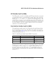
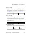
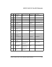
SPI Header (P2)
The SPI connector (P2) provides access to all of the SPI signals in the from
of a .1” spacing header. In addition, the FLAG1 signal can be used as a chip
select. If you are using FLAG1 as a chip select, disable the push button asso-
ciated with the flag. For more information, see “Push Button Enable
Switch (SW9)” on page 2-11.
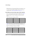
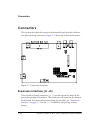
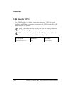
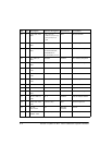
DAI Header (P3)
The DAI connector (P3) provides access to all of the DAI signals in the
from of a .1” spacing header. When using the header to access the DAI
pins of the processor, ensure that signals, which normally drive the DAI
pins, are disabled. Refer to “Codec Setup Switch (SW7)” on page 2-10 for
more information on how to disable signals already being driven from
elsewhere on the EZ-KIT Lite.
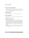
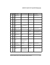
USB Connector (ZJ1)
The USB connector (ZJ1) allows to configure and program the processor.
Part Description Manufacturer Part Number
6-pin IDC header SULLINS GEC03DAAN
Part Description Manufacturer Part Number
26-PIN IDC HEADER BERG 54102-T08-13LF
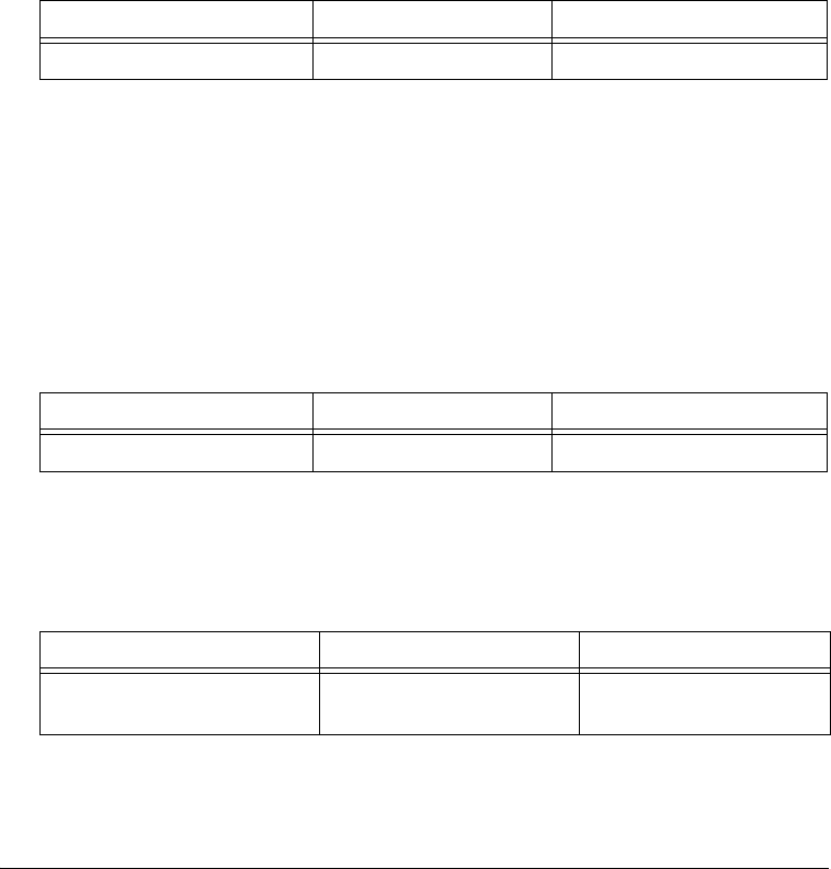
Part Description Manufacturer Part Number
Type B USB receptacle MILL-MAX
DIGI-KEY
897-30-004-90-000
ED90064-ND