


ADSP-21364 EZ-KIT Lite Evaluation System Manual 2-7
ADSP-21364 EZ-KIT Lite Hardware Reference
For information on how to disable the push buttons from driving the cor-
responding processor flag pin, see “Push Button Enable Switch (SW9)” on
page 2-11.
The
FLAG signals are available externally via the expansion interface con-
nectors (J1–3). The pinout of the connectors can be found in
“ADSP-21364 EZ-KIT Lite Schematic” on page B-1.
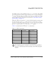
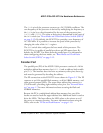
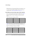
Expansion Interface
The expansion interface consists of three 90-pin connectors. Table 2-2
shows the interfaces each connector provides. For the exact pinout of the
connectors, refer to “ADSP-21364 EZ-KIT Lite Schematic” on page B-1.
The mechanical dimensions can be obtained from Technical or Customer
Support.
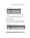
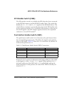
Table 2-1. IO FLAG Pins
FLAG Pin EZ-KIT Lite Function
FLAG0 SPI flash chip select
FLAG1 Push button (SW1) input
FLAG2 Push button (SW2) input
FLAG3 AD1835A’s SPI interface chip select
Table 2-2. Expansion Interface Connectors
Connector Interfaces
J1 5V, AD15–0
J2 3.3V, FLAG3–0, DAI_P20–1, SPI
J3 5V, 3.3V, reset, parallel port control signals