


Switch Settings
2-10 ADSP-21364 EZ-KIT Lite Evaluation System Manual
Codec Setup Switch (SW7)
The codec setup switch (SW7) can re-route signals going to the AD1835A
codec and can setup the communication protocol of the codec.
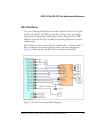
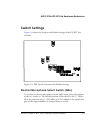
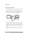
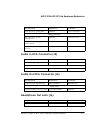
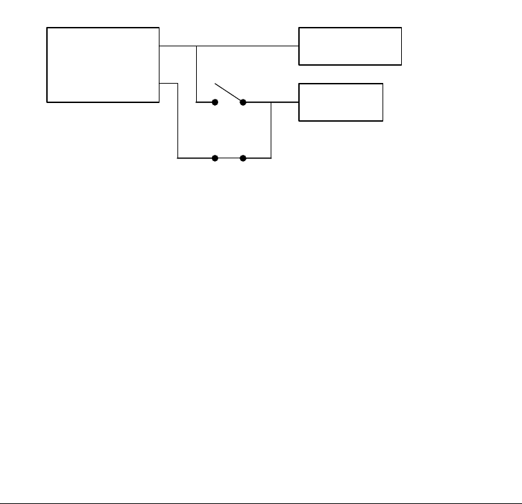
Positions 1 and 2 determine the clock routing for the audio oscillator to
the codec and to the processor. Figure 2-5 illustrates how the switch
positions 1 and 2 connect on the board. In the default position, route the
DAI_P17 pin to DAIP6 (in software) to clock the AD1835A.
Position 3 of the SW7 switch determines if the AD1835A device is a master
or is a slave. If the AD1835A is a master, the device’s serial interface gen-
erates the frame sync and clock signals necessary to transfer data. When
the device is a slave, the processor must generate the frame sync and clock
signals. By default, position 3 is ON, and the AD1835A generates the con-
trol signals.
Position 4 of
SW7 disconnects the AD1835A’s ADC_DATA pin from the DAI
interface. This is useful when the DAI interface connects to another
device.
Figure 2-5. Audio Clock Routing
AD1835 Codec
MCLK DAI_P6
ADSP-21364 Processor
DAI_P17
SW7.1
12.288MHz
OSC
SW7.2