


ADSP-21364 EZ-KIT Lite Evaluation System Manual 2-11
ADSP-21364 EZ-KIT Lite Hardware Reference
SPI Disable Switch (SW8)
The SPI interface switch (SW8) disables the SPI chip select lines connected
to the SPI flash memory and the AD1835A audio codec. The switch also
disables the ADC_LRCLK and ADC_BCLK signals on the AD1835A device. The
switch allows a customer to re-use the same pins on the SPI interface and
on the expansion interface. The SW8 default is all positions ON unless any of
the switch signals or the SPI interface signals are used on the expansion
connector or via an EZ-Extender
®
.
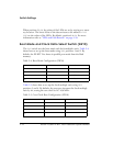
Push Button Enable Switch (SW9)
The push button enable switch (SW9) disconnects the push buttons from
the corresponding processor pins. This allows the signals to be used else-
where on the board. Table 2-3 shows the SW9 connections. By default, all
of the switch positions are ON.
Position 6 of SW9 connects or disconnects the latch-enable pin of the LED
to the logical
OR of the ~WE and ~LED_CS signals. When position 6 is OFF,
the latch-enable pin of the LED latch (U24) is pulled high, making the
latch transparent. In this position, the value of the LEDs is directly con-
nected to AD7–0.
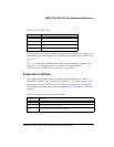
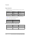
Table 2-3. Push Button Enable Switch (SW9) Connections
Switch Position Push Button Reference Designator Processor Pin
1
SW1 FLAG1
2 SW2 FLAG2
3 SW3 DAI_P19
4 SW4 DAI_P20