


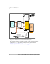
System Architecture
2-4 ADSP-21364 EZ-KIT Lite Evaluation System Manual
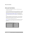
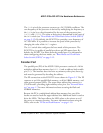
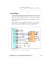
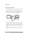
All of the PP signals are available externally via the expansion interface
connectors (
J1–3). The pinout of the connectors can be found in
“ADSP-21364 EZ-KIT Lite Schematic” on page B-1.
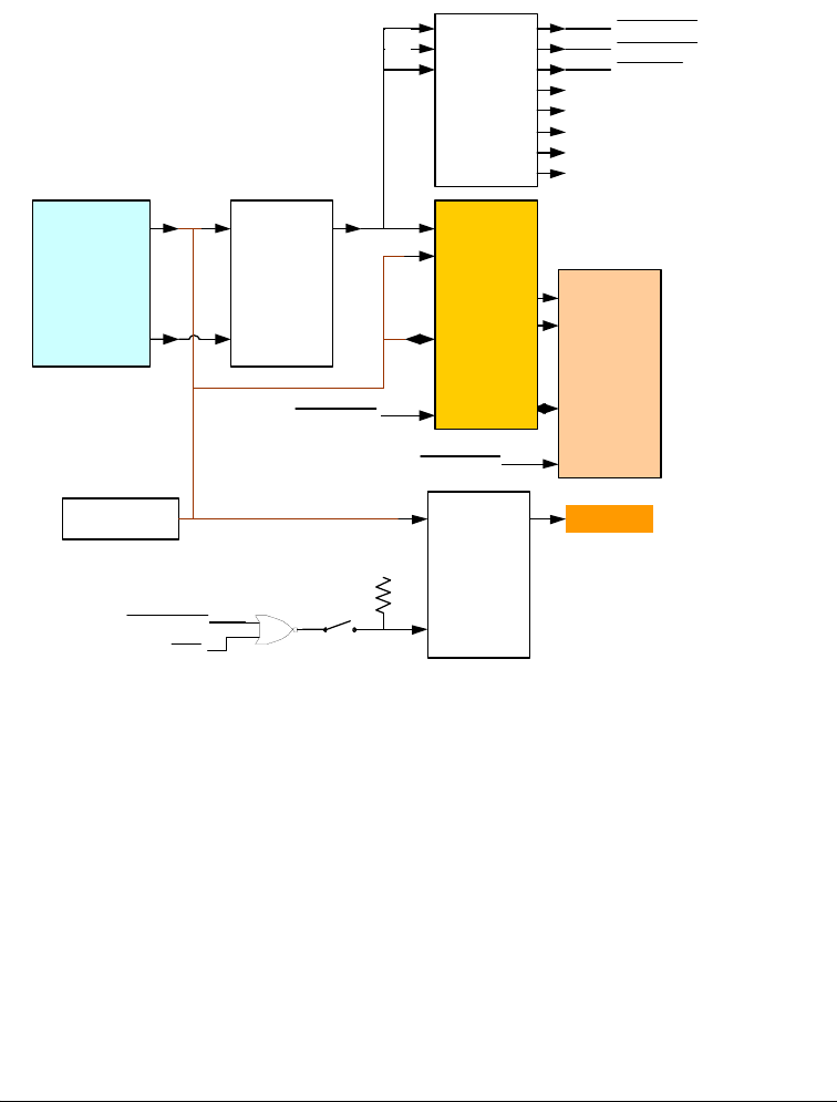
Figure 2-2. Parallel Port Connections Block Diagram
DSP
AD15-0
Expansion
Interface
ALE
373
8-bit
Latch
LE
DQ
373
8-bit Latch
(2)
LE
D
Q
512KB
SRAM
D7-0
A8-18
A0-7
CS
8 LED s
Opening the switch
puts latch always in
Transparent Mode
1MB
FLASH
D7-0
A8-19
A0-7
CS
FLASH_CS
SRAM_CS
WR
SRAM_CS
FLASH_CS
SRAM_CS
LED_CS
138
3->8
DEC
0
2
1
3
4
5
6
7
C
B
A
D0-7
A23
A22
A21