


14 Installation Guide APC BC300 Series 40kW 208/450/480V UPS
990-1401
Installation
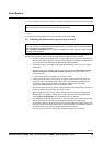
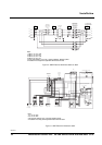
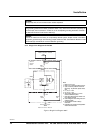
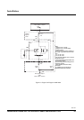
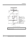
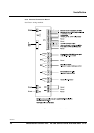
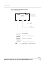
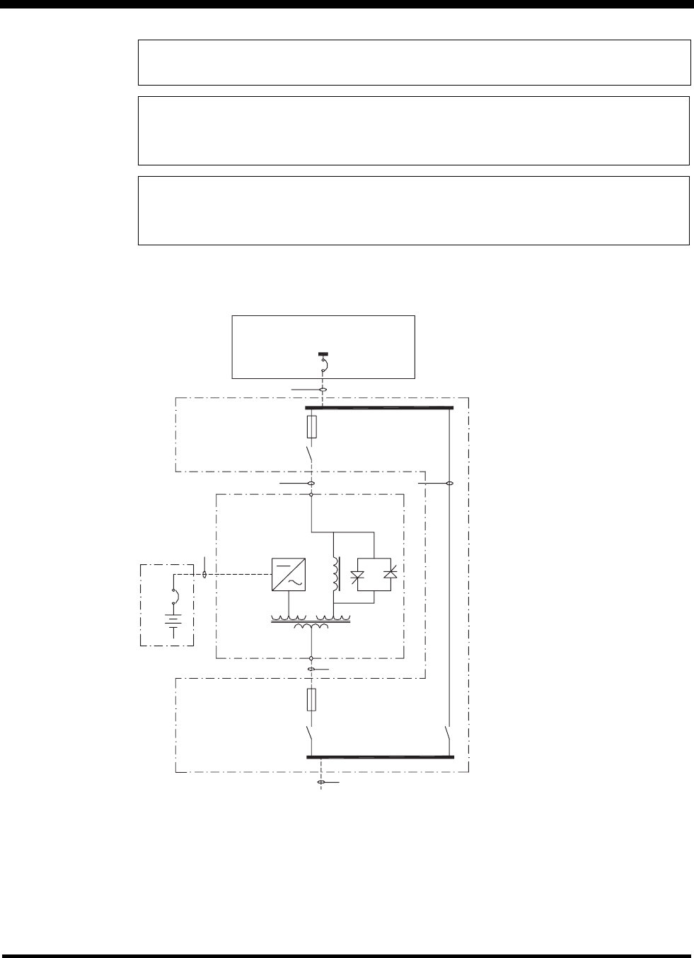
3.3.4 Single Line Diagram for BC300
Figure 7 Single Line Diagram 208V
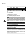
NOTICE!
Always keep AC, DC and communication cables separated.
NOTICE!
The grounding electrode conductor (Protective Earth - PE) must be the same size (ampacity) as
the UPS input circuit conductors. Conduit is not an acceptable grounding electrode conductor -
see National Electrical Code Section 250-91(a).
NOTICE!
The unit is wired from the factory as a separately derived system. Output neutral is bonded to
equipment ground through main bonding jumper inside the UPS. See National Electrical Code
Article 250-5(d) and 250-26 for correct installation grounding.
Notes:
1. Must be 3- or 4-wire.
2. Must be 3 or 4 cabling provided by others.
3. Input overcurrent protection is based on
80% rating - any deviation, please contact
APC.
4. F1, F2, F3 = 120A
5. F4, F5, F6 = 170A
6. All AC power cabling is 3- or 4-wire +
Ground at 208VAC 3-phase.
7. UPS output cables and input cables must
be in separate conduits.
8. Power wiring and control wiring must be in
separate conduits.
9. See installation manual for battery
information.
10. Installation must comply with all applicable
national and local codes.
Utility Source (provided by others)
208V 3 or 4 Wire + Ground
MIB
Service
Bypass
Panel
F4, 5, 6
UIF
Q001
UIS
UPS
F1, 2, 3
UOF
Q002
UOS
Q003
BS
UPS System Output
208V 3 or 4 Wire + Ground
111A
40kW
111A
111A
161A
161A
200AT
200A
250AT