


Adjustments Geometry - 15
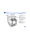
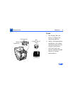
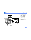
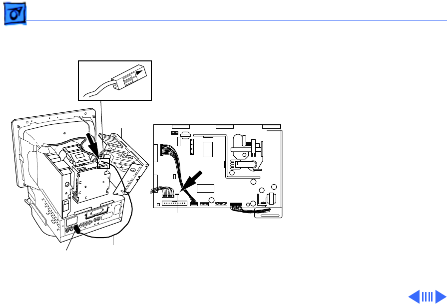
1 Remove the three
Phillips screws that
secure the analog board
to the chassis.
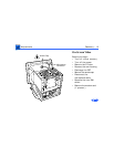
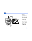
2 Tilt the analog board
back, being careful not
to put stress on the
cables.
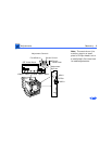
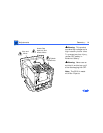
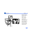
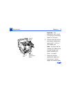
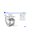
3 Locate jumper P805
(Rev. A) or P102
(Rev. B) near the logic
board connector on the
lower left corner of the
analog board.
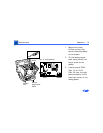
Rev A Analog Board
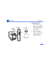
Analog
Board
Monitor
Adjustment
Cable
Modem
Port
P805
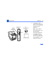
P805