


HARDWARE INSTALLATION
45
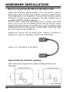
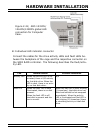
The intelligent LED controller outputs a low-level pulse to deter-
mine if status LEDs are attached to pin sets 1 and 2. This allows
automatic controller conguration of the LED output. If the logi-
cal level is different between the st 2 sets of the HDD LED header
(LED attached to Set 1 but not Set 2), the controller will assign the
rst HDD LED header as the global indicator connector. Otherwise,
each LED output will show only individual drive status.
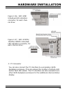
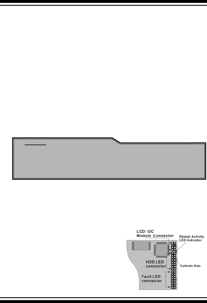
The SATA RAID controller provides four kinds of LED status connec-
tors.
A: Global indicator connector, which lights when any drive is active.
B: Individual LED indicator connector, for each drive channel.
C: I
2
C connector, for SATA proprietary backplane enclosure.
D: SGPIO connector for SAS Backplane enclosure
The following diagrams and description describes each type of con-
nector.
Note:
A cable for the global indicator comes with your computer
system. Cables for the individual drive LEDs may come with
a drive cage, or you may need to purchase them.
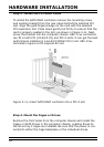
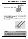
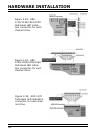
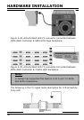
A: Global Indicator Connector
If the system will use only a single global indicator, attach the
global indicator cable to the two pins HDD LED connector. The fol-
lowing diagrams show the connector and pin locations.
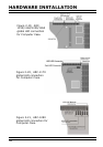
Figure 2-18, ARC-
1110/1120/1210/1220
global LED connection
for Computer Case.