


2001 Microchip Technology Inc. DS39024B-page 11
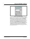
Using the PICDEM 17 Monitor
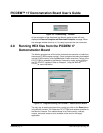
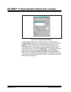
2.9 Running Diagnostics on the PICDEM 17
Demonstration Board
The Monitor firmware on the PIC17C756A provides several diagnostic
routines that allow the user to run pretested code on a peripheral. The
diagnostics include:
• A/D – The A/D diagnostic allows the user to configure the A/D channel,
clock source, justification, and reference. The A/D results are displayed
in the Monitor message window.
During A/C Diagnostics, the switches and LEDs take on the following
functions:
• Capture – The capture diagnostic allows the user to configure the
capture channel and mode. The capture results are displayed in the
Monitor message window.
During Capture Diagnostics, the switches and LEDs take on the follow-
ing functions:
• FLASH – The external FLASH memory diagnostic simply writes all
zero’s, all one’s, checkerboard, and inverse checkerboard to a portion
of memory and checks to make sure that the values were properly
written. This diagnostic does not require any user interaction.
• I
2
C – This diagnostic writes an incrementing count to the 24LC01B
Serial EEPROM on the PICDEM 17 demonstration board and verifies
that each location has been properly programmed. This diagnostic does
not require any interaction from the user.
S5 Increment channel number, 0 – 11 only
S9 Toggle between internal and external voltage
references
S10 Toggle between right and left justify
S12 The clock source (F
OSC/8, FOSC/32, FOSC/B4, FRC)
D1, D6 – D8 Channel number in HEX format
D9 Internal (OFF) or External (ON) voltage references
D10 Left (OFF) or Right (ON) justify
D11 – D12 A/D clock source
The diagnostic ends when Halt is clicked
S5 Increment capture channel, 1 – 4 only
S9 Increment toggle mode
D1, D6 Capture channel
D9, D10 Capture mode
The diagnostic ends when Halt is clicked