


PICDEM™ 17 Demonstration Board User’s Guide
DS39024B-page 12 2001 Microchip Technology Inc.
• LCD – This diagnostic configures I/O pins and writes a message to the
external LCD panel in 4-bit mode.
If this diagnostic is selected and these I/O pins are not connected to the
LCD panel, then the message will not be displayed correctly. Provided
the connections are correct, the diagnostic does not require any interac-
tion from the user.
• PWM – This diagnostic allows the user to select the PWM channel and
increment or decrement the period and duty cycle of that channel.
During PWM Diagnostics, the switches and LEDs take on the following
functions:
• Switches – This diagnostic tests the functionality of the memory
mapped switches and LEDs. Each time a switch is pressed the corre-
sponding LED is turned OFF. This diagnostic ends when all LEDs have
been turned OFF.
• USART2 – This diagnostic writes a message to the Monitor program
running on the PC Host. This diagnostic does not require any interac-
tion from the user.
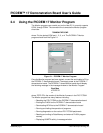
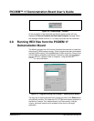
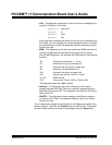
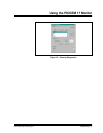
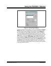
To run a diagnostic, highlight the desired test in the Diagnostics window of the
Monitor program. Then click the Execute button to start the test. Those tests
that do not automatically terminate can be stopped using the Stop button.
portF<0:3> data lines
portG<1> E
portG<0> R/W
portF<7> RS
S5 Increments the channel, 1 – 3 only
S7 Decrement the duty cycle down to 0
S8 Increment the duty cycle, no upper limit
S9 Decrement the period down to 0
S10 Increment the period, no upper limit
S12 Selects clock source, Timer1 or Timer2
D1, D6 PWM channel
D12 Timer source Timer1 (OFF) or Timer2 (ON)
The diagnostic ends when Halt is clicked